

Here are some installation case studies for the GRF167-Y37-4P-50.69-M4-270 reducer.
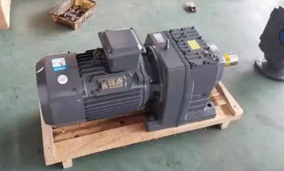
Here are some installation examples of GRF167-Y37-4P-50.69-M4-270 reducers:Case 1: Installation in a certain chemical mixing equipment
Installation environment: Installed in a chemical workshop with a certain amount of corrosive gas, the ground is relatively flat but there is slight vibration.
Installation steps:
Firstly, according to the installation dimensions of the reducer, corresponding installation holes are machined on the frame of the mixing equipment to ensure that the flatness and perpendicularity of the installation plane meet the requirements.
Install the reducer onto the frame through the M4 flange, and use a spirit level to adjust the levelness of the reducer to ensure it is in a horizontal state. Then gradually tighten the anchor bolts in diagonal order, using a torque wrench to ensure that the tightening torque of the bolts meets the regulations.
Connect the motor and reducer, first clean the mating surfaces of the motor output shaft and the reducer input shaft, then align the axis centerlines of the motor and reducer to ensure that the coaxiality error is within the allowable range, and finally install and tighten the coupling bolts.
Connect the output shaft of the reducer to the mixing shaft, and connect the two through a suitable coupling, ensuring coaxiality and installing anti loosening devices.
Attention: Due to the presence of corrosive gases in the workshop, the outer shell of the reducer has been treated with anti-corrosion measures, and the condition of the seals has been regularly inspected to prevent corrosive gases from entering the interior of the reducer.
Case 2: Installation of conveying equipment in a certain mine
Installation environment: The mining environment is relatively harsh, with a lot of dust and significant vibration during equipment operation.
Installation steps:
Before installation, reinforce the installation foundation by pouring concrete onto a sturdy foundation platform and reserving anchor bolt holes on the platform.
Place the reducer on the foundation platform, use a spirit level and shims to adjust the levelness and height of the reducer, so that the output shaft is at the same height as the drum shaft of the conveying equipment. Then insert the anchor bolts, pre tighten them first, and tighten them with a torque wrench according to the specified torque after adjusting the position.
The connection between the motor and the reducer adopts an elastic coupling to buffer the impact force during equipment startup and operation. Strictly control the coaxiality during installation to ensure smooth operation of the motor and gearbox.
Install a sprocket on the output shaft of the reducer and connect it to the roller sprocket of the conveying equipment through a chain. When installing the sprocket, pay attention to the installation accuracy of the sprocket and ensure that the tension of the chain is appropriate.
Attention: To prevent dust from entering the gearbox, a dust cover is installed at the ventilation hole of the gearbox. At the same time, due to the high vibration of the equipment, regularly check the tightening of the anchor bolts to prevent them from loosening.
Case 3: Installation in a food processing production line
Installation environment: The food processing workshop requires high hygiene conditions, relatively clean environment, and certain temperature and humidity control.
Related News


