
Collaborative debugging of sizing machine reducer and frequency converter: practical method to solve the problem of multi axis synchronization
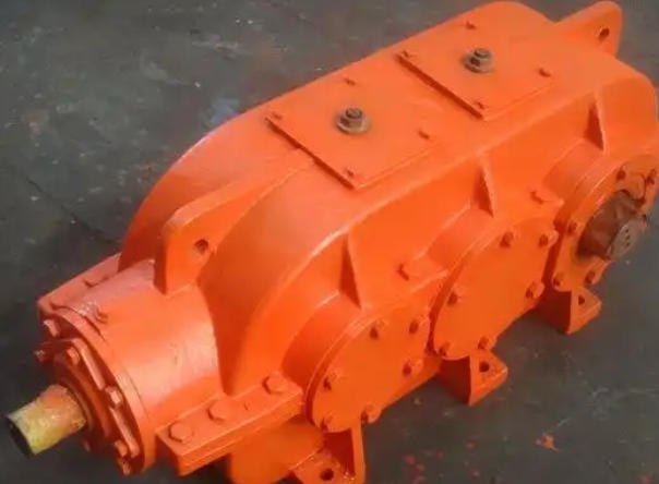
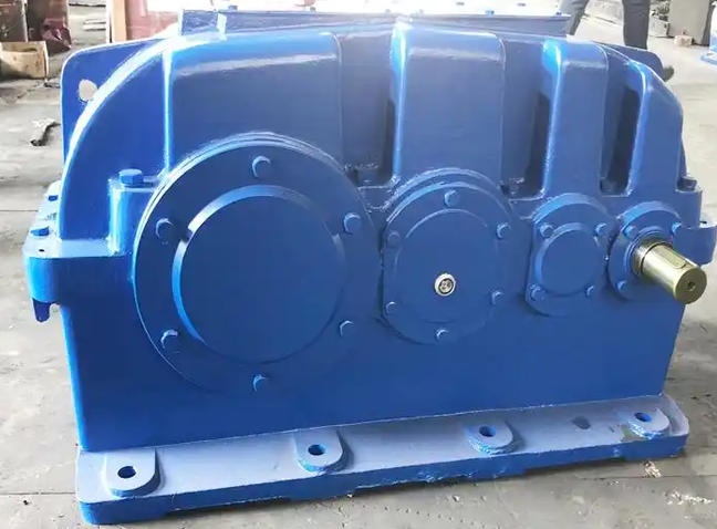
1、 Hardware installation and mechanical parameter confirmationGearbox and transmission ratio setting: Accurately calculating and setting the mechanical transmission ratio is the foundation. It is necessary to accurately set the speed ratio between the winding motor and the reel provided by the equipment manufacturer (such as setting the F1.00 parameter). If the reduction ratio is not accurate, it will directly affect the accuracy of the roll diameter calculation and tension control.
Encoder installation and selection: The tension control motor must be equipped with a high-precision rotary encoder (recommended to use products with 600 wires or above) as the speed feedback of the frequency converter. Be careful during installation to avoid causing excessive impact and damage to the encoder. At the same time, it is necessary to ensure that the encoder coupling is securely fastened to prevent slipping during high-speed operation.
2、 Core parameter tuning of frequency converter
Motor tuning and parameter matching: Before tuning the motor, it is necessary to disconnect the motor from the load (reducer) to ensure no-load tuning. Accurately input parameters according to the motor nameplate. If the motor cannot rotate for a long time during tuning, it indicates that the parameters are seriously inconsistent or the motor has a fault. After tuning is completed, it is necessary to focus on checking the identified motor no-load current, which should normally be within the range of 30% to 50% of the rated current.
Control mode selection: The tension control of the sizing machine must adopt closed-loop vector control mode (such as setting F0.02=1). If mistakenly set as an open-loop vector, the system is prone to unstable phenomena such as "carriage return".
Inertia tuning and compensation: Disconnect the motor from the deceleration system for no-load inertia self-learning. Due to the significant increase in the rotational inertia of the winding device with the increase of the winding diameter, it is necessary to set a reasonable material inertia compensation coefficient (such as FC.11 parameter) to compensate for the additional torque required to overcome the material's rotational inertia during acceleration and deceleration, and prevent the spool from reversing or tension fluctuations.
3、 System integration and PID optimization
Speed synchronization signal connection: Connect the analog output port (corresponding to the output frequency) of the main traction frequency converter to the analog input terminal of the tension frequency converter as a speed synchronization control signal to ensure real-time synchronization between the winding line speed and the main speed.
Fine tuning of PID parameters: The tuning of tension PID parameters is a meticulous and repetitive process. Usually, two sets of PID parameters need to be set: PID1 is used to improve fast tracking and response at low speeds, and PID2 is used to maintain smooth operation at high speeds. During debugging, the PID parameters can be adjusted based on the range of linear velocity changes and set to linear velocity.
Roll diameter calculation and dynamic compensation: Enable the roll diameter calculation function (based on linear velocity calculation method), and use recursive operations to accurately calculate the roll diameter in real time. During specific dynamic processes such as hollow roll activation, acceleration and deceleration, and parking, torque compensation and anti breakage programs are added to ensure constant tension from small to large rolls.