

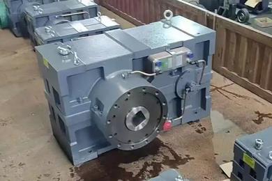
ZLYJ250-16 reducer ensures precise alignment between the output shaft and the screw shaft of the extruder during installation
Here are some methods to ensure precise alignment between the output shaft and the screw shaft of the rubber screw extruder when installing the ZLYJ250-16-I reducer:Preparation and inspection before installation
Check the dimensional accuracy of components: Accurately measure the diameter, length, keyway, and other dimensions of the output shaft of the reducer and the screw shaft of the rubber screw extruder to ensure that the dimensional deviation is within the design requirements. At the same time, check the surface flatness and roundness of the shaft, and there should be no obvious machining defects or deformations.
Clean the connection parts: Use appropriate cleaning agents to wipe off rust proof oil, oil stains, and impurities from the output shaft of the reducer, the connecting flange, and the screw shaft connection parts of the rubber screw extruder to ensure the tightness of the connection.
Use appropriate installation tools and methods
Using centering tools: specialized centering tools such as laser centering instruments, centering rods, and centering sleeves can be used. When using a laser alignment device, install the laser emitter on the output shaft of the reducer and the receiver on the screw shaft. By adjusting the laser beam to align with the center of the receiver, the alignment of the two axes can be achieved.
Adopting a reasonable assembly process: If a coupling is used for connection, first install half of the coupling on the output shaft of the reducer and the other half on the screw shaft, and then adjust the position of the coupling to achieve alignment between the two shafts. During installation, rough tapping with hammers or other tools is prohibited. The internal threads of the assembly fixture and end shaft can be used to press the transmission parts in with the force of the bolt to avoid damaging the shaft and bearings.
Accurate adjustment during installation process
Adjust the levelness of the rack: First, place the rack on a flat foundation and use a high-precision level to calibrate and adjust the levelness of the rack, ensuring that the rack is on the same plane and providing a stable foundation for the installation of the reducer and extruder.
Preliminary positioning of reducer: Install the reducer on the frame, measure and adjust it to make the center height of the reducer output shaft roughly the same as the center height of the rubber screw extruder screw shaft, and use shims or other tools for fine adjustment.
Precise alignment adjustment: connect the reducer and extruder barrel, and then measure the coaxiality and perpendicularity of the two shafts by measuring the distance between the reducer output shaft end and the relevant position of the barrel, or use a dial indicator and other measuring tools, and make accurate adjustment according to the measurement results until the specified accuracy requirements are met.
Inspection and confirmation after installation
Manual turning inspection: After installation, manually rotate the input shaft of the reducer to drive the output shaft and screw shaft to rotate. Check whether the rotation is smooth, whether there is any jamming or abnormal resistance, and observe whether the relative position of the two shafts has changed.
Trial operation inspection: Conduct a no-load trial operation, observe the operation of the reducer and extruder, and check for any abnormal noise, vibration, or heating. If there is any abnormality, the machine should be stopped immediately for inspection and the alignment should be readjusted.
Related News


