
What Are the Best Ways to Optimize the Installation Conditions of the ZLY140-8-1 Reducer?
The
key to improving the installation environment of the ZLY140-8-1
hard-tooth-face gear reducer lies in strictly controlling temperature,
minimizing vibration, ensuring precise alignment, and maintaining
protective conditions. These measures are essential to guarantee its
long-term stable operation.
1. Temperature Environment Optimization
The operating ambient temperature should be strictly maintained between -40°C and 45°C. If the ambient temperature drops below 0°C, the lubricating oil must be preheated to above 0°C before startup to prevent inadequate lubrication from damaging the gears or bearings. In high-temperature environments (approaching 45°C), enhanced ventilation or forced cooling devices, such as cooling fans or cooling coils, should be installed. This prevents excessive oil temperatures from degrading lubrication performance and shortening the gearbox's lifespan.
2. Installation Foundation and Vibration Reduction Measures
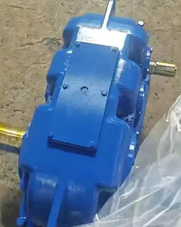
The installation surface must be flat, rigid, and leveled using a precision spirit level (with a levelness tolerance of ≤ 0.2mm/m). This prevents uneven stress on the housing, which can lead to abnormal gear meshing. High-strength anchor bolts should be used, accompanied by rubber shock absorbers and anti-loosening nuts. Bolts must be tightened in a diagonal sequence to prevent loosening caused by operational vibrations. If the equipment is located in a vibration-prone area (e.g., near large motors or stamping presses), it is highly recommended to add an independent concrete foundation or a dedicated vibration-isolation pedestal to block external vibration transmission.
The installation surface must be flat, rigid, and leveled using a precision spirit level (with a levelness tolerance of ≤ 0.2mm/m). This prevents uneven stress on the housing, which can lead to abnormal gear meshing. High-strength anchor bolts should be used, accompanied by rubber shock absorbers and anti-loosening nuts. Bolts must be tightened in a diagonal sequence to prevent loosening caused by operational vibrations. If the equipment is located in a vibration-prone area (e.g., near large motors or stamping presses), it is highly recommended to add an independent concrete foundation or a dedicated vibration-isolation pedestal to block external vibration transmission.
3. Precise Alignment and Transmission Connection
Ensuring strict coaxiality between the motor shaft, the gearbox input shaft, and the load output shaft is critical. The radial deviation should be kept within ≤ 0.1mm, and the angular deviation within ≤ 0.05°, to avoid premature wear caused by misalignment. Elastic couplings are recommended to compensate for minor deviations. If a hydraulic coupling is utilized, it should be positioned at the motor end, while an elastic coupling must be installed at the reducer's input end to protect the more delicate input shaft.
Ensuring strict coaxiality between the motor shaft, the gearbox input shaft, and the load output shaft is critical. The radial deviation should be kept within ≤ 0.1mm, and the angular deviation within ≤ 0.05°, to avoid premature wear caused by misalignment. Elastic couplings are recommended to compensate for minor deviations. If a hydraulic coupling is utilized, it should be positioned at the motor end, while an elastic coupling must be installed at the reducer's input end to protect the more delicate input shaft.
4. Protection and Cleanliness Management
The reducer should be installed away from sources of acid/alkali corrosion, excessive dust, and sewage discharge. If avoidance is impossible, isolation and protective barriers, such as PP boards, must be installed to prevent shell corrosion. Regularly clean the surface and ventilation openings of the gearbox to ensure optimal heat dissipation, and routinely inspect the seals to prevent dust or moisture ingress.
The reducer should be installed away from sources of acid/alkali corrosion, excessive dust, and sewage discharge. If avoidance is impossible, isolation and protective barriers, such as PP boards, must be installed to prevent shell corrosion. Regularly clean the surface and ventilation openings of the gearbox to ensure optimal heat dissipation, and routinely inspect the seals to prevent dust or moisture ingress.
5. Lubrication and Oil Level Monitoring
After installation, inject lubricating oil that meets the manufacturer's specifications. The oil level should be maintained between the upper and lower limits of the dipstick or at the center of the oil sight glass. For enhanced reliability, consider installing oil temperature monitoring and oil level alarm systems. This enables early warning of abnormalities and elevates the level of intelligent operation and maintenance.
After installation, inject lubricating oil that meets the manufacturer's specifications. The oil level should be maintained between the upper and lower limits of the dipstick or at the center of the oil sight glass. For enhanced reliability, consider installing oil temperature monitoring and oil level alarm systems. This enables early warning of abnormalities and elevates the level of intelligent operation and maintenance.
Related News