
Introduction to Working Principle for RV40-15-0.18KW Worm Gear Reducer
The RV40-15-0.18KW is a compact worm gear reducer from the small RV series. It realizes speed reduction and torque multiplication via meshing engagement between the worm and worm wheel. Matched with 0.18kW low-power motors, this unit is widely deployed in light-load, low-speed automated machinery. Its working principle can be explained in three sections: transmission structure, power transfer process, and key performance features.
1. Transmission Structure Assembly
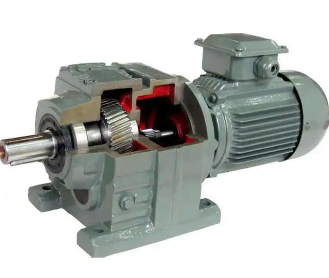
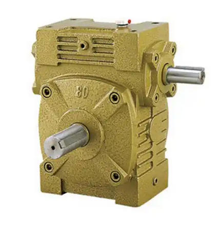
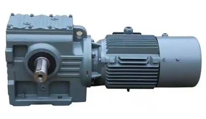
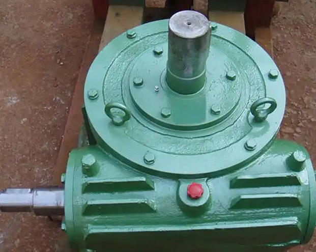
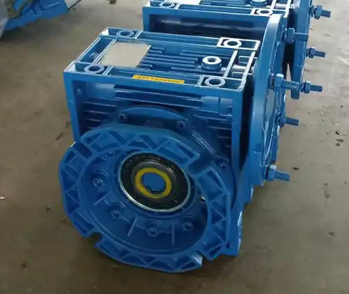
This reducer assembly consists of a worm, worm wheel, aluminum alloy casing, input/output shafts, bearings and oil seals. (1) The worm serves as the driving part. It is manufactured from quenched hardened steel and generally adopts an Archimedean spiral tooth profile. It can be directly coupled to the motor shaft or connected via a coupling. (2) The worm wheel acts as the driven member. Fabricated from wear-resistant tin bronze, its teeth precisely mesh with the worm’s spiral profile and are mounted on the output shaft. (3) The model designation indicates core parameters: 40 refers to the 40 mm center distance, 15 stands for the 15:1 reduction ratio, and 0.18KW means the matching motor power rating. The unit features a highly compact footprint.
2. Motion and Torque Transfer Workflow
(1) Power input: The 0.18kW motor delivers high-speed, low-torque power to the reducer worm shaft and spins the worm at high rotational speed. (2) Meshing speed reduction: The worm’s helical teeth engage with the worm wheel teeth. The worm’s rotary movement is converted into rotation of the worm wheel by helical tooth thrust. For this 15:1 ratio variant, a single-start worm pairs with a 15-tooth worm wheel. The worm must complete 15 revolutions to turn the worm wheel once, achieving a 15× speed reduction. (3) Torque multiplication: Based on power conservation (excluding transmission losses), torque and rotational speed are inversely proportional. This reducer runs at roughly 0.5–0.6 transmission efficiency. After speed reduction, output torque rises to 7.5–9 times the input torque to satisfy light-load equipment power demands. (4) Power output: Rotation of the worm wheel drives the output shaft and delivers amplified torque to downstream loads, for example small belt conveyors and sorting mechanisms.
3. Core Transmission Characteristics
(1) Constant reduction ratio: It maintains a fixed 15:1 gear ratio with accurate transmission and steady running without slippage. (2) Partial self-locking limitation: For this 15:1 model, the worm lead angle normally exceeds 3.5°. It fails to satisfy the self-locking condition where the lead angle is smaller than the equivalent friction angle, so reliable self-locking cannot be achieved. When power cuts off, gravity or external forces may reverse the load. A brake should be fitted according to site operating conditions. (3) Quiet and smooth operation: Line contact occurs during worm and worm wheel meshing. This minimizes impact and vibration during operation. Typical running noise stays below 60dB, making the reducer suitable for noise-sensitive applications including laboratory and medical equipment.