

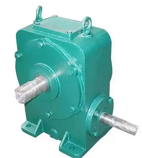
Installation steps of WD250-53-V worm gear reducer
The installation of WD250-53-V (center distance of 250 mm, i ≈ 53, single-stage, V-shaped installation) follows the standard process of "preparation → foundation and positioning → alignment → lubrication and ventilation → running in and loading", with a focus on rigid foundation, double plane precision alignment, correct oil injection, and temperature rise monitoring.Standard installation steps:
1. Unpacking and Inspection
Verify that the nameplate matches the model; Check if the appearance, oil seal, and transportation plug of the ventilator are intact; Count the attachments.
2. Installation environment and foundation
Dry and well ventilated, with a maintenance space of ≥ 500mm around; The ambient temperature is -5 to+40 ℃.
Rigid foundation, with a levelness of ≤ 0.1 mm/m; Use anchor bolts and secondary grouting; First rough adjustment, then fine adjustment.
3. Positioning and foot fastening
Lifting and positioning; Tighten the foot and flange when they are different to prevent deformation of the machine body; Tighten gradually diagonally to the specified torque.
4. Input shaft alignment (motor end)
Double table method or laser alignment; Parallel offset ≤ 0.05 mm; angular deviation ≤ 0.02 mm/m; Measure and record in two perpendicular planes.
Choose a suitable elastic coupling and control the deviation according to its compensation amount and the instruction manual.
5. Output shaft assembly (working machine end)
Prohibition of hammering; Priority should be given to using threaded holes/tooling for pressing; Ensure axial freedom of the output shaft without additional axial constraints.
After assembly, manual turning should be smooth and free of jamming.
6. Lubrication and ventilation
Inject oil according to the instruction manual's brand and oil level (about 2/3 of the oil window when shutting down); Loosen/replace the vent plug before operation (remove transport blockage).
If it is V-shaped (worm side/upper), the oil level and lubrication method should be checked according to the installation position, and forced lubrication or cooling should be added if necessary.
7. Electrical and Safety
The inlet of the junction box is facing downwards; Confirm that the phase sequence and rotation direction are consistent with the working machine; Set overload/temperature rise protection.
8. Empty running in
1–3 h, Monitor temperature rise, noise, vibration, and leakage; Temperature rise ≤ 60 K; abnormal shutdown investigation.
9. Graded loading and acceptance
25% → 50% → 75% → 100%, shift up after each level stabilizes; Recheck the oil level, temperature rise, and connection tightness.
Retain alignment reports, oil level/quality records, temperature rise curves, and vibration data.

