

What are the installation steps of ZLYJ250-16-I reducer on rubber screw extruder
The installation steps of ZLYJ250-16-I reducer on rubber screw extruder are as follows:Preparation before installation
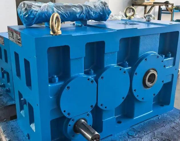
Check whether the appearance of the reducer is intact, whether all components are complete, and whether there is any damage caused during transportation.
Prepare the necessary tools for installation, such as wrenches, screwdrivers, level gauges, feeler gauges, lifting equipment, as well as installation materials such as lubricants, sealants, etc.
Ensure that the installation environment meets the requirements, the installation position is flat and stable, there is sufficient space around for maintenance and repair of the gearbox, and good ventilation.
Determine the installation location and installation foundation
According to the structure and design requirements of the rubber screw extruder, the appropriate installation position of the reducer should be determined, taking into account the connection method between the reducer and the screw extruder, the layout of the transmission device, and the convenience of operation and maintenance.
Foundation construction should be carried out at the selected installation location, and the foundation should be flat, firm, and able to withstand the weight and vibration of the reducer and extruder during operation. According to the model and size of the reducer, determine the size and fixing method of the foundation, usually requiring reserved anchor bolt holes.
Install the gearbox
Use lifting equipment to place the reducer steadily in the installation position, so that the output shaft of the reducer is roughly aligned with the screw shaft of the rubber screw extruder.
Use a spirit level to calibrate the gearbox horizontally, ensuring that it is in a horizontal state to ensure its normal operation and even meshing of the gears.
Fix the reducer on the foundation with anchor bolts. When tightening the anchor bolts, gradually tighten them in diagonal order to ensure that the reducer is firmly installed and evenly stressed, avoiding deformation or damage caused by installation stress.
Connect the transmission device
If a coupling is used to connect the reducer and the screw shaft of the rubber screw extruder, first install half of the coupling on the output shaft of the reducer and the other half on the screw shaft. During installation, attention should be paid to the installation accuracy of the coupling, ensuring that it fits tightly with the two shafts and the coaxiality meets the requirements.
Use tools such as a dial gauge to accurately align the coupling, so that the coaxiality error between the output shaft of the reducer and the screw shaft is controlled within the allowable range. Generally, it is required that the radial runout and axial tilt do not exceed the specified values. The allowable centering error varies for different types and specifications of couplings, and specific values can be determined by referring to the coupling manual.
If it is connected through a transmission device such as a pulley or sprocket, ensure that the installation position of the pulley or sprocket is accurate and the tension of the transmission belt or chain is appropriate. For V-belt transmission, when the V-belt is initially installed, the midpoint of the tight edge should be able to deform by 8-10mm under an external force of 2-3 kilograms.
Lubrication and debugging
After installation, add an appropriate amount of lubricating oil that meets the requirements to the gearbox. The model and filling amount of lubricating oil can refer to the user manual of the gearbox. Generally speaking, after the first 300-600 hours of use, the oil should be changed once, and then every 3000 hours thereafter.
Perform no-load test run on the reducer and rubber screw extruder to check the operating status of the reducer, including whether the sound is normal, whether there is abnormal vibration, whether the bearing temperature is too high, and the circulation of lubricating oil. At the same time, observe whether the operation of the transmission device is smooth, and whether there is any looseness or deviation in the coupling, pulley or sprocket.
After the no-load trial run is normal, conduct a load trial run, gradually increase the working load of the extruder, observe the operation of the reducer under different loads, check whether its transmission efficiency and load-bearing capacity meet the requirements, and whether the working status of each component is stable. During the load test run, attention should be paid to monitoring the oil temperature, oil pressure and other parameters of the gearbox to ensure that they are within the normal range.
Related News


