

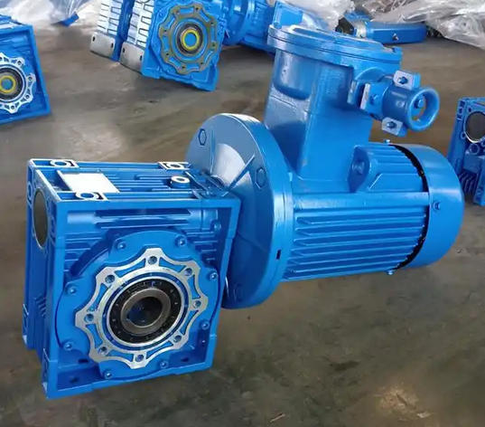
How to determine whether the concentricity between the output shaft and load shaft of NMRVO90F1-2.2KW reducer meets the standard
To determine whether the concentricity between the output shaft and load shaft of the NMRVO90F1-2.2KW reducer meets the standard, the core is to use the "radial deviation+angular deviation" dual index detection, combined with operational status verification, and finally compare it with industry standards for judgment.1. Clearly define the standards for compliance (core basis)
Radial deviation (axis center offset): ≤ 0.1mm. Due to the power of 2.2KW, this model of reducer requires strict control of the offset to avoid vibration.
Angular deviation (inclination of the shaft): ≤ 0.05mm/m, meaning that the end face runout per meter of length does not exceed 0.05mm.
Auxiliary standards for operating status: no abnormal vibration, no sharp noise, and no significant heating of the coupling (temperature ≤ 60 ℃).
2. Core detection tools and operation steps
(1) Tool preparation
Essential tools: 0-10mm range dial gauge (accuracy 0.01mm), magnetic gauge holder, level, feeler gauge.
Auxiliary tools: wrench (for fixing the shaft), clean cloth (for cleaning the surface).
(2) Radial deviation detection
Clean the surface of the shaft: Wipe the outer circles of the output shaft and load shaft of the reducer, remove oil and rust, and ensure a smooth detection surface.
Fixed dial gauge: Attach the magnetic gauge holder to the output flange of the reducer, place the dial gauge probe vertically on the outer circle of the load shaft, pre press 1-2mm and adjust to zero.
Synchronize the rotation of two axes: Use a wrench to slowly rotate the two axes (maintaining synchronization without relative displacement), and record the maximum and minimum readings of the dial gauge during one rotation.
Calculation deviation: Radial deviation=(maximum reading - minimum reading)/2, and a result of ≤ 0.1mm is considered compliant.
(3) Angular deviation detection
Adjust the dial gauge: Place the dial gauge probe vertically on the flange end face of the load shaft (near the edge to avoid the influence of the center hole), pre press 1mm and adjust to zero.
Uniform rotation detection: Rotate both axes synchronously once and record the maximum and minimum reading difference of the dial gauge.
Conversion angular deviation: reading difference ÷ flange diameter × 1000, the result is ≤ 0.05mm/m to meet the standard (e.g. flange diameter 100mm, reading difference ≤ 0.005mm).
3. Operational status verification (auxiliary judgment)
No load test run: After installation, run the equipment without load for 30 minutes and observe whether there is periodic vibration or abnormal noise.
Loading test run: Gradually load to rated load, run for 1 hour, touch the coupling and bearing end cover, and there is no abnormal heating (not hot to the touch).
Shutdown re inspection: After loading and running, stop the machine and check the radial and angular deviations again. If there is no obvious rebound (deviation change ≤ 0.02mm), it is considered stable and meets the standard.
Related News


