

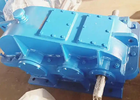
How to ensure safe operation of equipment when adjusting the axis lines of input and output shafts of ZL1000-8-3 soft tooth surface reducer
When adjusting the axis lines of the input and output shafts of the ZL1000-8-3 soft tooth reducer, the following measures can be taken to ensure the safe operation of the equipment:Accurate measurement and adjustment
Using appropriate tools: An electronic level with an accuracy of 0.02mm/m can be used to measure horizontal deviation, and the coaxiality of the input shaft and motor shaft, as well as the output shaft and load end, can be detected by a laser alignment instrument. It is recommended to control the radial deviation within 0.05mm and the angular deviation ≤ 0.1 °.
Measurement deviation: Use a dial gauge to measure shaft deviation and angular deviation. Rotate the coupling halves 180 degrees simultaneously to eliminate surface errors. The dial gauge pointer should not move significantly on the measurement surface. Divide the deviation value displayed by the dial gauge pointer by 2 to obtain the value of shaft deviation; By calculating the average of the two differences, the numerical value of the angle deviation can be obtained.
Calculate adjustment amount: Based on the measured radial displacement and axial displacement, calculate the axial adjustment amount and radial adjustment amount based on the principle of similar triangles, and then adjust them by adding or removing shims.
Considering the effect of thermal expansion: The operating temperature of single-stage, two-stage, and three-stage reducers is usually between 80 ℃ and 90 ℃, which can cause the axis to rise and the axis center distance to expand, while the operating temperature of the motor is lower than that of the reducer. Therefore, when performing shaft alignment, the centers of the high-speed and low-speed shafts of the reducer should be slightly lower than the centers of the motor shaft and the driven shaft to compensate for the deviation caused by thermal expansion.
Ensure installation and operation standards
Installation and fixation: During the adjustment process, it is necessary to ensure that the reducer is firmly fixed to the installation base, avoid movement, and maintain the level and stability of the equipment to avoid additional stress and deformation.
Adjustment sequence: Priority should be given to axial adjustment to ensure that the end face clearance of the coupling meets the requirements of the equipment manual, followed by radial adjustment to correct the left and right/up and down offset of the axis, so that the total radial deviation is within the allowable range. After the adjustment is completed, measure the radial displacement and axial displacement again according to the measurement method, calculate the total radial deviation and axial deviation, and confirm that the adjustment results meet the requirements.
Safe operation: Before repairing or adjusting the gearbox, the power must be cut off and wait for it to completely stop rotating to avoid operators wearing loose clothing, long hair, or hanging objects to prevent accidental injury.
