

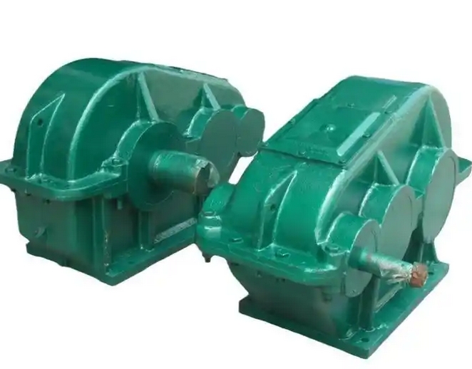
Here is an introduction to the installation process of the heat dissipation fins for the soft gear surface JZQ250-10.35-9 reducer.
The following is the general installation process for the cooling fins of JZQ250-10.35-9 reducer with soft tooth surface:preparation
Confirm parts: Check whether the model and specifications of the heat sink match the gearbox, and whether there are any defects such as damage or deformation. At the same time, prepare the necessary bolts, nuts, washers, and other connectors for installation, ensuring that they are sufficient in quantity and of good quality.
Cleaning components: Clean the surface of the reducer housing and the installation area of the heat sink with a clean cloth or solvent, remove impurities such as oil, dust, rust, etc., ensure that the installation surface is clean and flat, and facilitate the tight fit between the heat sink and the reducer housing.
Preparation tools: Prepare installation tools such as wrenches, screwdrivers, vernier calipers, etc. If necessary, also prepare tools such as angle grinders for slight polishing or trimming of the installation site.
Positioning and installation
Position determination: Determine the installation position of the heat sink based on the structure and heat dissipation requirements of the reducer. Generally speaking, the heat sink should be installed on the side or top of the gearbox housing where it is easy to dissipate heat, and should not affect the normal operation and maintenance of the gearbox.
Installation bracket (if any): If the heat sink is equipped with an installation bracket, first fix the bracket on the gearbox housing. Use bolts or welding to firmly install the bracket in the predetermined position, ensuring a tight connection between the bracket and the gearbox housing without any looseness. During the installation process, it is necessary to use tools such as a level or ruler to check the levelness and verticality of the bracket. If there is any deviation, it should be adjusted in a timely manner.
Fixed heat sink: Place the heat sink on the mounting bracket (or directly on the installation position of the gearbox housing if there is no bracket), aligning the mounting holes of the heat sink with the screw holes on the bracket or gearbox housing. Then, use bolts, nuts, and washers to secure the heat sink tightly. When tightening the bolts, they should be gradually tightened diagonally to ensure that the heat sink is evenly stressed and tightly adhered to the bracket or gearbox housing, avoiding gaps that affect the heat dissipation effect.
Inspection and adjustment
Check installation firmness: After installation, check the fixing of the heat sink again to ensure that all bolts are tightened and there is no looseness or shaking between the heat sink and the bracket or gearbox housing.
Check the spacing between heat sinks: If multiple heat sinks are installed, it is necessary to check whether the spacing between the heat sinks is uniform and consistent, to avoid too small spacing affecting air circulation or too large spacing causing waste of heat dissipation area. If necessary, the position of the heat sink can be fine tuned.
Clean up the installation site: Clean up any debris and debris generated during the installation process to maintain a clean working environment.
When installing the cooling fins of the JZQ250-10.35-9 reducer with soft tooth surface, if you are unsure of the specific installation method, you can refer to the reducer's user manual or consult relevant technical personnel.
Related News


