
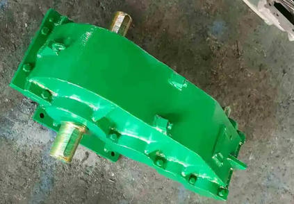
How to select the installation posture for the WPDKA80-60 worm gear reducer
1、 Preferred posture: Horizontal and horizontal foot installationThe installation surface should be kept level, with a longitudinal levelness error of ≤ 0.1mm/m, and calibrated using a level with an accuracy of 0.02mm/m.
In this posture, the oil tank completely covers the worm gear meshing area, providing the most thorough lubrication and avoiding local dry wear. It is suitable for over 90% of conventional conveying, packaging, and light industrial transmission conditions.
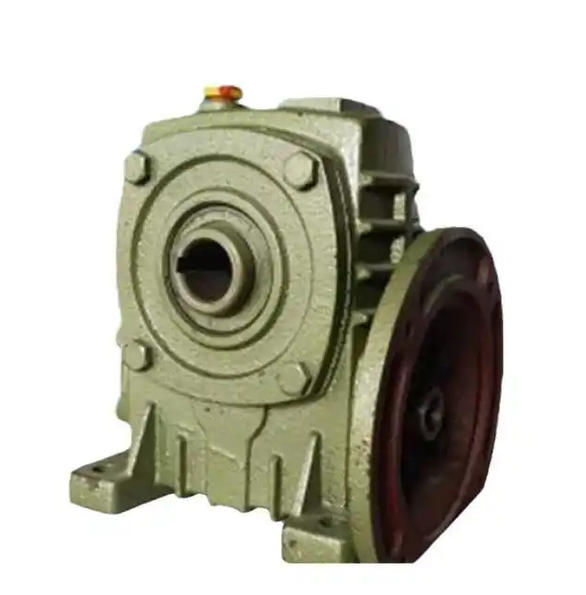
The foot bolts are fastened diagonally in three rounds, and the concrete grade of the base is ≥ C30, with a thickness not less than 12 times the diameter of the foot bolts, to ensure that there is no vibration deviation during operation.
2、 Adaptation posture for special working conditions
Vertical downward installation of output shaft: Only used in vertical transmission scenarios with limited space. It is necessary to confirm that the ventilation cap is located at the highest point of the box and the oil level is adjusted to the upper limit of the sight glass to avoid bearing oil shortage.
Small angle tilt installation: When the tilt angle is ≤ 15 °, it can operate normally. The oil level height needs to be recalculated to ensure that the worm gear tooth surface is completely immersed in the lubricating oil. If the tilt angle exceeds 15 °, the manufacturer must be contacted to confirm the lubrication compatibility.
Prohibited posture: It is strictly prohibited to install the input shaft vertically downwards and the oil tank completely deviating from the worm gear meshing area in an inverted manner, which will directly cause lubrication failure and rapid wear of the worm gear.
3、 Key points for posture selection core verification
1. Regardless of which posture is chosen, ensure that the oil level sight glass is in a convenient side position for observation, and that the oil does not overflow from the vent cap during operation.
2. The axis alignment deviation is controlled within radial ≤ 0.05mm and axial displacement ≤ 0.02mm, with a reserved thermal compensation of about 0.15mm.
3. After installation is completed, manually turn the wheel 3 times to confirm that there is no jamming and that the oil can reach the mating surface smoothly, and then start the no-load trial run.
Related News