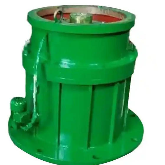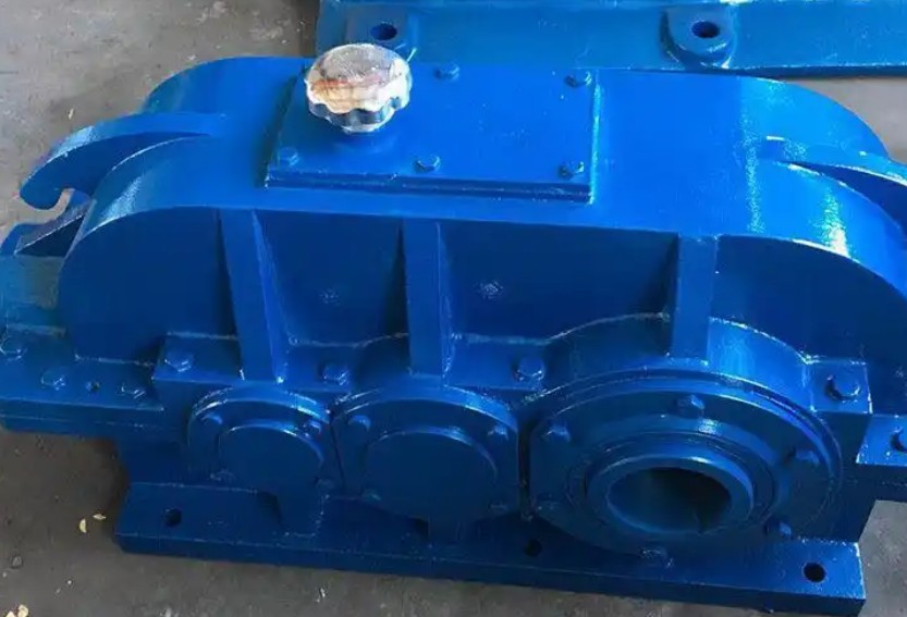

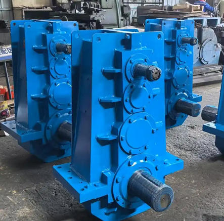
How to avoid improper adjustment of different shaft degrees in the soft ZD50-7-II gear reducer with soft tooth surface
1、 Pre prevention and control measures before adjustmentEliminate soft foot hazards: Use a feeler gauge to check the contact between the reducer, motor/load base, and foundation. All feet should not be suspended, and the single foot gap should be ≤ 0.03mm to avoid force rebound after adjustment.
Basic accuracy verification: Use a precision level to measure the levelness of the gearbox body, with a deviation of ≤ 0.1mm/m, an installation surface roughness Ra ≥ 6.3 μ m, and no burrs, oil stains, or rust.
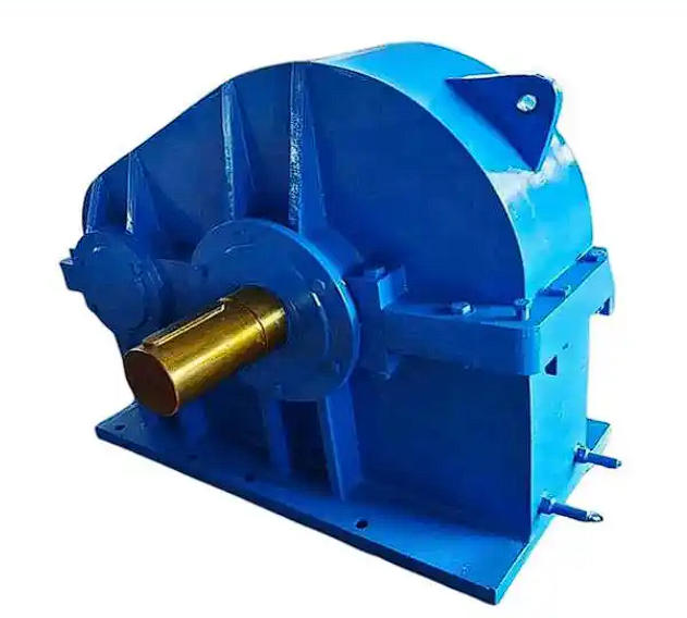
Tool calibration and verification: Pre calibrate the dial gauge and laser alignment instrument to ensure measurement accuracy within 0.01mm, avoiding tool errors that may cause adjustment errors.
Component status inspection: Check the coupling for wear, cracks, and deformation, and ensure that the shaft end is not damaged or bumped. Confirm that the shaft itself is not bent or deformed, and eliminate hardware defects from the source.
2、 Step by step calibration with strict tolerance control
Coarse centering positioning: Use a ruler to lean against the outer circle of the two halves of the coupling, and control the height difference of the outer circle within 0.1mm by increasing or decreasing the foot pad; Measure the distance between the end faces of the coupling with a caliper, adjust the displacement bolts to ensure that the end face clearance difference is ≤ 0.2mm, and allow the two shafts to enter the adjustable reference range.
Precision locking for precise alignment: Priority is given to using the dial gauge dual gauge method, with the radial gauge and axial gauge installed at a 90 ° angle. The two axes are rotated synchronously 360 °, and readings are recorded every 45 °. Three consecutive readings with a difference of ≤ 0.02mm are considered effective. Finally, the radial deviation is controlled at ≤ 0.05mm and the angle deviation is ≤ 0.02mm/m.
Reserve for thermal expansion compensation: The compensation amount for carbon steel shafts is calculated based on a linear expansion coefficient of 11.5 × 10 ⁻⁶/℃. During cold alignment, the center of the reducer side shaft is slightly lower than the center of the motor/load shaft by 0.1-0.15mm to offset the secondary deviation caused by the axis floating up after heating up during operation.
Synchronous verification of tooth flank clearance: Measure the tooth flank clearance using lead pressure method or dial gauge method, and control it within the range of 0.1~0.3mm to avoid meshing bias caused by shaft alignment deviation. The soft tooth surface has weak resistance to bias load, and exceeding the clearance limit will accelerate the plastic deformation of the tooth surface.
3、 Tightening and dynamic verification
Standardize bolt tightening: Tighten the anchor bolts evenly in 2-3 diagonal steps, with a torque error of ≤ 5%, to avoid unilateral force causing axis displacement and rebound.
Static retest confirmation: Immediately retest the coaxiality after tightening to confirm that there is no rebound in the deviation and it is still within the tolerance range. It is strictly prohibited to start the machine without retesting.
Dynamic hot state verification: Run the equipment without load for 1-2 hours, and after the equipment is thermally stable, retest the vibration speed to be ≤ 4.5mm/s and the temperature rise to be ≤ 40 ℃. After running with load for 2 hours, recalibrate again. If the thermal state deviation change is ≤ 0.02mm, it is considered qualified.
4、 Key points for avoiding pitfalls
It is strictly prohibited to rely on elastic couplings to compensate for large deviations. Elastic components can only offset small errors of ≤ 0.2mm and cannot replace precise alignment.
It is prohibited to carry out centering operations in environments with strong vibrations and drastic temperature fluctuations to avoid measurement data distortion.
The thickness of the stainless steel gasket used for adjustment should be controlled between 0.1~0.5mm, and the number of gaskets in a single set should not exceed 3 to prevent deformation caused by overlapping gaskets and loss of accuracy.