

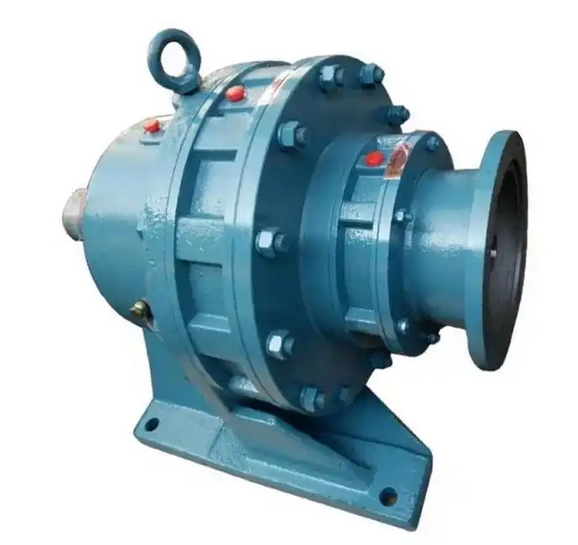
The installation steps for the double-stage XWED42-187-0.55KW cycloidal pinwheel reducer are as follows:
The installation steps for the two-stage XWED42-187-0.55KW cycloidal pinwheel reducer are as follows:Preparation before installation
Check the equipment: Confirm whether the reducer and motor are intact, and check whether the dimensions and fitting tolerances of the motor positioning boss, input shaft, and reducer connection parts match.
Cleaning parts: Clean the anti rust oil at the connection between the motor input shaft, positioning boss, and reducer with gasoline or zinc sodium water to ensure tight connection and flexible operation.
Determine installation location: Choose a safe, stable, easy to operate and maintain location that will not be affected by external impacts.
Internal component installation (if disassembled or assembled gearbox)
Check the cycloid gear: The cycloid gear is measured in pairs. Check whether the two cycloid gears can completely overlap, including the bearing hole, shaft pin hole, and external gear type. At the same time, confirm the front and back of the cycloid gear, and the marked side should face upwards.
Installation of cycloidal gear: Rotate a piece of cycloidal gear 180 degrees and place it into the needle gear housing, paying attention to the misalignment of the outer teeth to ensure smooth rotation and no swinging after insertion.
Install eccentric bearings and spacer rings: Place the eccentric bearings in such a way that the bearing holes of the lower cycloid fully accommodate the cylindrical balls of the eccentric bearings, and then insert the spacer rings.
Install another cycloid gear: Place the other cycloid gear in the marked position, ensuring that the marked side faces upwards and is offset 180 degrees from the mark on the lower cycloid gear.
Insert the shaft sleeve: Place the corresponding shaft sleeve in the hole of the cycloid wheel, rotate it by hand, and check if the installation is correct. If it can rotate smoothly, the internal parts installation is completed.
Overall installation
Connect the motor: Connect the motor naturally to the reducer, ensuring that the reducer output shaft is concentric with the motor input shaft and the outer flange is parallel. The keyway of the motor shaft should be perpendicular to the fastening bolt.
Tighten bolts: First tighten the installation bolts in the opposite direction but do not tighten them, then tighten the other bolts one by one, and finally rotate the tension bolts. All fastening bolts should be manually fixed and checked with a torque wrench according to the fixed torque data.
Connecting cables: Connect the power cord to the power port of the gearbox to ensure a reliable and stable cable connection.
Fixed reducer: Use bolts to fix the reducer in the installation position, ensuring that the bolts are securely fastened. If necessary, the position of the reducer can be fine tuned by adjusting the bolts to ensure installation accuracy and smooth operation.
After installation, acceptance work such as torque test and noise test can be carried out to check whether the reducer is running normally. If there are any problems, they should be promptly investigated and adjusted.

