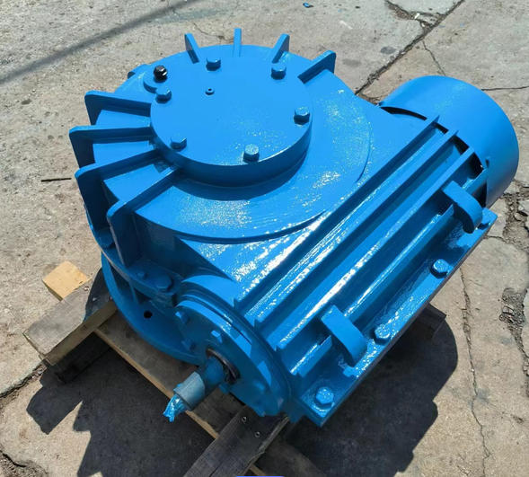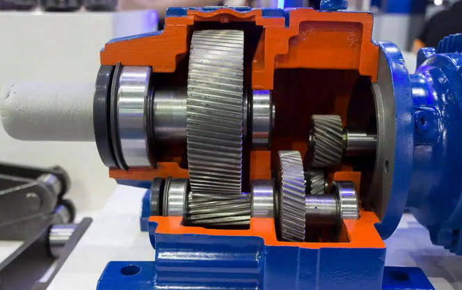


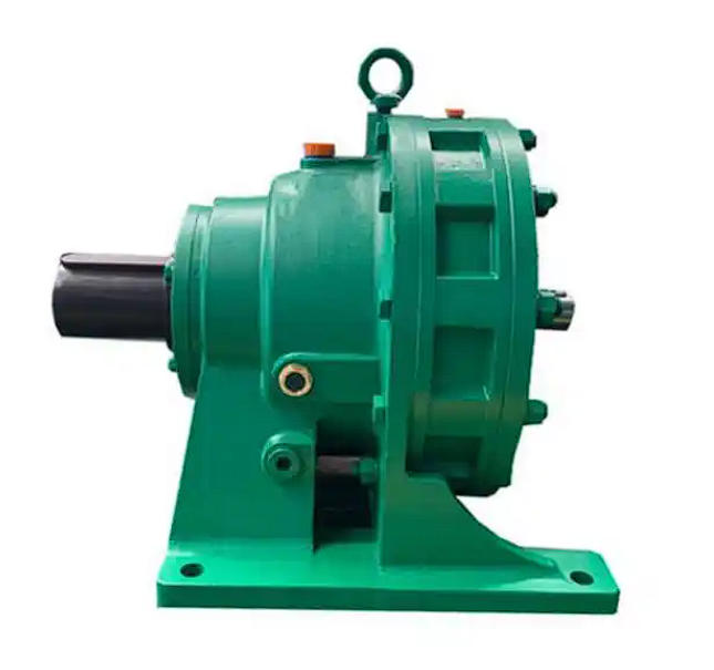
How to determine whether the output shaft of the BWD2-35-1.5KW cycloidal reducer and the inner hole of the coupling have an interference fit
1、 Preliminary assessment of drawings and tolerance zonesFirst, verify that the standard shaft diameter of the BWD2 model output shaft is 35mm, and confirm the fitting tolerance code indicated on the drawing.
If the fit is marked as H7/s6 or H7/r6, the tolerance zone of the hole completely falls below the tolerance zone of the shaft, which belongs to standard interference fit.
If labeled as H7/k6, it belongs to transitional fit, and only slight interference will occur under some working conditions, not in a fully interference state.
2、 Precision dimension verification after disassembly
This is the most accurate judgment method and the ultimate basis in engineering:
Measure the actual shaft diameter in two radial directions at 90 ° on the upper, middle, and lower sections of the output shaft fitting section using a micrometer, and take the average value.
Measure the actual size of the inner hole of the coupling at the corresponding position using an inner diameter dial gauge, and take the average value.
Calculate the difference: inner hole size - shaft diameter size. A negative value indicates interference fit, while a positive value indicates clearance fit.
The reasonable interference fit of the BWD2 model's mating position is usually controlled at 0.01~0.03mm, which meets the requirements of heavy-duty torque transmission.
3、 Reverse validation of assembly process
If the coupling can be manually pushed into the shaft without external force during assembly, it indicates clearance or transitional fit, not interference fit.
If the coupling must be pressed in with a press or heated to 80-120 ℃ during assembly before it can be smoothly fitted in place, and after cooling, the coupling firmly holds the shaft shoulder without any axial movement, it can be determined as an interference fit.
It is strictly prohibited to directly hammer and violently assemble, as interference fit and forced cold tapping can easily cause bending and deformation of the output shaft.
4、 Non disassembly on-site auxiliary verification
After the power is cut off and the machine is stopped, the magnetic gauge holder is fixed on the reducer base, and the dial gauge probe is pressed against the outer circle of the coupling.
The axial fixed output shaft is completely locked, and a pry bar is used to pry the outer circle of the coupling in the circumferential direction. The radial reading of the dial gauge shows no change, indicating that there is no gap and most likely an interference fit.
If the dial gauge shows a radial runout of ≥ 0.02mm when prying, it indicates that there is a gap and the interference fit clamping effect has been lost.
There is no periodic impact noise in the coupling during operation, and there is no visible relative rotation during start stop, which can also serve as effective auxiliary evidence for interference fit.