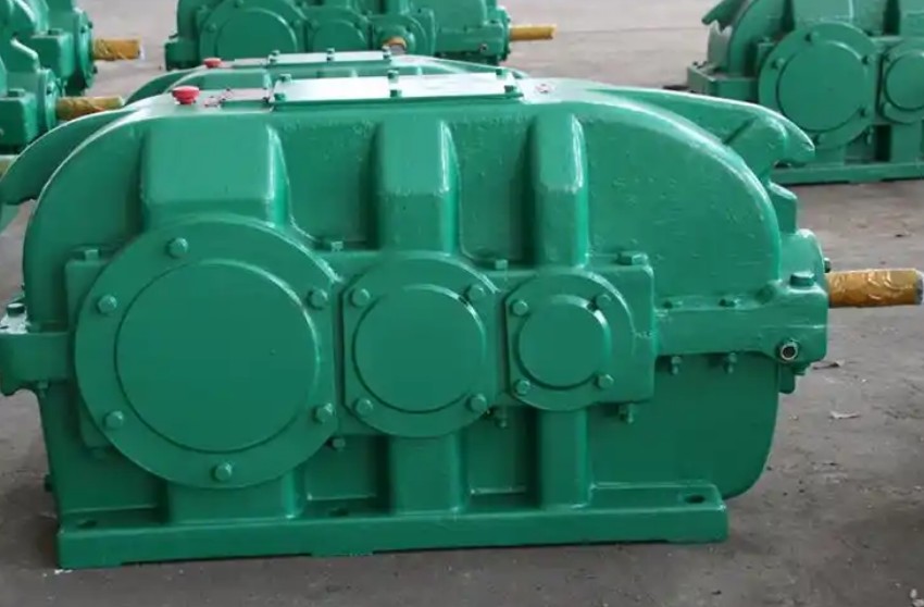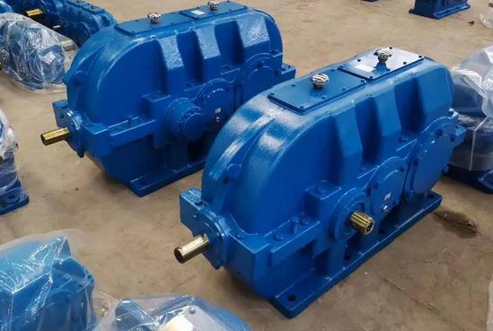


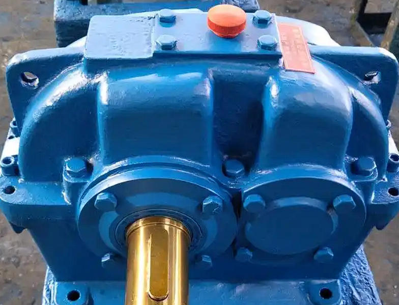
What are the operating steps for debugging the ZDY hard tooth reducer housing
1、 Preparation before debugging1. Installation and alignment inspection: Ensure that the installation base of the reducer is flat and rigid enough. Use a laser centering instrument or dial gauge to calibrate the coaxiality of the motor and reducer, and the radial deviation is usually required to be ≤ 0.05mm.
2. Lubrication system confirmation: Check whether the model (such as ISO VG 220 or 320) and viscosity of the lubricating oil meet the requirements. Check the oil level and keep it at the centerline position of the oil gauge (or 1/2 to 2/3 of the height of the oil gauge) in a stationary state.
3. Manual turning and safety inspection: Disconnect the output load, manually rotate the input shaft, and confirm that it rotates flexibly, without jamming or abnormal noise. At the same time, check whether safety devices such as protective covers and couplings are installed properly.
2、 No load trial operation
1. Start and steering confirmation: jog the motor to confirm that the rotation direction is consistent with the gearbox identification. Three phase motors require a phase sequencer to verify the phase sequence.
2. No load operation monitoring: Start at 25% of rated speed, gradually increase to full speed, and run continuously for 4-6 hours. During this period, it is necessary to focus on monitoring the following parameters:
Temperature rise: The temperature of the bearing area should be ≤ 75 ℃ (or not exceed the ambient temperature+40 ℃), and the oil temperature should be ≤ 80 ℃.
Vibration value: The radial vibration of the input shaft should be ≤ 2.8mm/s.
Noise: The sound pressure level at a distance of 1 meter from the equipment should be ≤ 85dB (A), the sound should be uniform, and there should be no high-frequency whistling or periodic impact sound.
3、 Hierarchical load debugging
After normal no-load operation, test in stages at 30%, 60%, and 100% rated load, with each stage running continuously for a period of time (such as 2 hours):
1. 30% load: Focus on checking whether there is any oil leakage at each sealing point (such as shaft seal, box joint surface).
2. 60% load: Use a thermal imaging device to detect the temperature distribution of the box. If there is local overheating, it may indicate excessive bearing preload.
3. 100% load:
Record the fluctuation of motor current, with a deviation of less than 5%.
Check the contact spots of the gear pair, which should reach at least 60% tooth length and 40% tooth height. Otherwise, adjust the gasket to correct the meshing position.
4、 Fine tuning of key parameters
Gear backlash control: Use lead wire method or dial gauge to measure the tooth backlash. The standard side clearance of a hard tooth reducer is usually (0.05-0.08) mn (modulus). If the clearance is too large, it will cause impact noise, while if it is too small, it will cause abnormal wear.
Optimization of bearing clearance: It is recommended to control the axial clearance of tapered roller bearings within 0.1-0.15mm. It can be corrected by adding or removing adjusting shims. If the clearance is too large, it will reduce transmission accuracy, and if it is too small, it will exacerbate temperature rise.
Coupling compensation adjustment: The allowable deviation for diaphragm couplings is ≤ 0.05mm, and for elastic pin couplings it is ≤ 0.1mm. Dynamic balance testing is also required for high-speed transmission applications.
Related News