
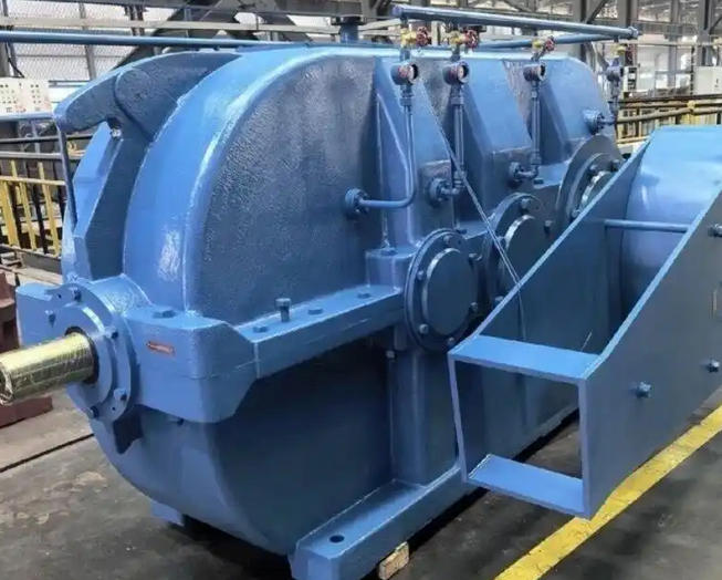
Critical Warnings for ZD Series Motor-Reducer Integration
Pre-Installation Preparation and Inspection
Component Verification and Surface Cleaning: Before commencing the assembly, thoroughly inspect both the motor and
the gearbox for any transit damage. It is imperative to verify that all
mating dimensions, particularly the motor's locating spigot, input
shaft, and the reducer's input bore, strictly adhere to the specified
tolerances. Utilize a lint-free cloth and a suitable solvent, such as
gasoline or zinc-sodium based cleaner, to meticulously remove all
anti-rust oils, dust, and debris from the motor shaft, spigot, and
reducer flange. This critical step ensures a flush fit, optimal runout
accuracy, and prevents premature wear.
Key Removal: Prior to coupling the motor to the reducer, the key on the motor shaft must be completely removed to facilitate a proper friction-lock connection.
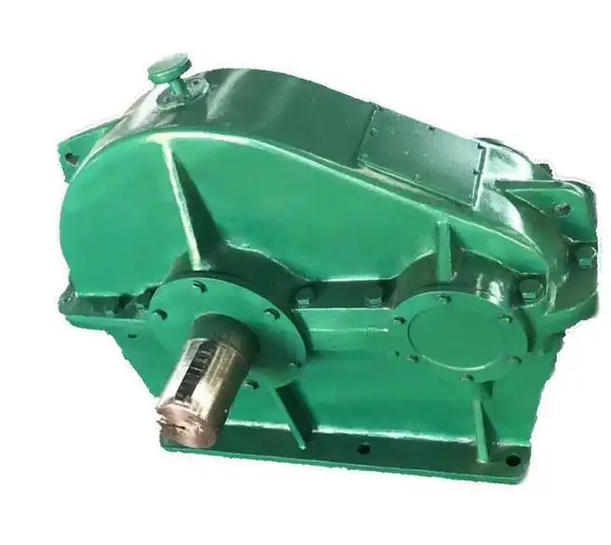
Assembly and Alignment Protocols
Precision Alignment: During the mating process, absolute concentricity between the motor
input shaft and the reducer input bore must be maintained, ensuring that
both outer flanges remain perfectly parallel. Any misalignment will
introduce severe radial loads, potentially leading to motor shaft
fracture or accelerated gear wear.
Prohibition of Impact Tools: Under no circumstances should hammers or other percussive tools be used
to force the components together. Such brute force can inflict
irreversible damage to internal bearings and gear sets. Always rely on
smooth, manual insertion or specialized pressing tools.
Torque Sequence and Fastening: To guarantee uniform clamping force, adopt a cross-pattern tightening
sequence. Initially, hand-thread the bolts at diagonal corners without
tightening. Subsequently, insert the remaining diagonal bolts. Proceed
to tighten all four mounting bolts gradually in a crisscross pattern
using a calibrated torque wrench to the manufacturer's specified values.
Only after the flange bolts are fully torqued should the input bore's
clamping (set) screws be tightened.
Lubrication and Friction Surface Management
Friction Interface Restrictions: Do not apply any lubricants to the internal friction bands or the
friction surfaces at the output end of the internal gears. Introducing
oil to these areas will critically compromise the friction-locking
torque and lead to slippage.
Internal Greasing: The internal gear train requires a high-quality, temperature-resistant
synthetic grease. Ensure the grease fill volume is strictly limited to
approximately 1/3 of the internal cavity capacity to prevent churning
losses and overheating.
Trial Run and Post-Installation Validation
No-Load Testing Protocol: Once the assembly is complete and the lubricant level is verified,
initiate a no-load trial run. This conditioning phase must last for a
minimum duration of two hours to allow the lubricant to distribute
evenly and to verify mechanical integrity.
Operational Monitoring: Throughout the trial run, the system must operate smoothly without any
signs of impact, excessive vibration, abnormal acoustic emissions, or
oil leakage. Should any anomalies be detected, the equipment must be
shut down immediately for troubleshooting. Following the initial run-in
period, re-inspect the oil level and seal integrity to account for any
potential settling or minor seepage.