

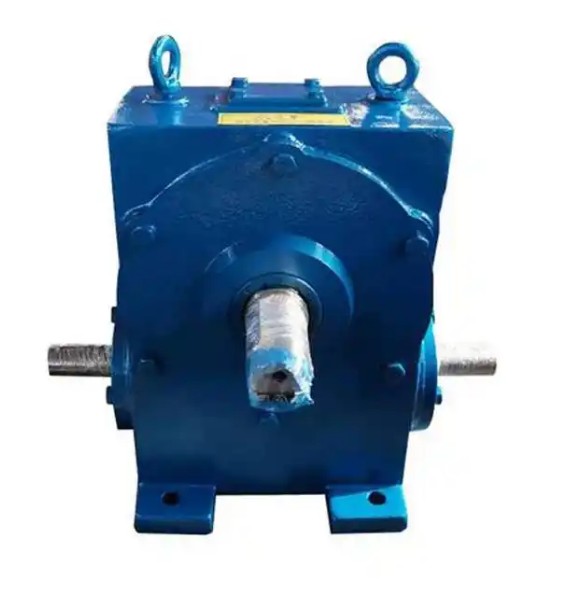
How to correctly install and adjust WD150-47-Ⅱ worm gear reducer
The correct installation and adjustment method for WD150-47-II worm gear reducer is as follows:
1、 Preparation before installation
1. Verify the model WD150-47-II, inspect the appearance for any bumps, cracks, or oil leaks, and ensure that the output and input shafts are not bent or deformed.
2. Clean the installation foundation, coupling, and keyway to ensure that there are no iron filings, burrs, or oil stains.
3. Check the lubricating oil level: Generally, a small amount of anti rust oil is included in the factory. Before formal use, the special oil for worm gear and worm gear (VG220 or VG320) must be replaced, and the oil level should be increased to 1/2 to 2/3 of the oil gauge.
4. Check the rotation direction: The manual turning is easy and flexible, without any jamming or abnormal friction.
2、 Installation and alignment (most crucial)
1. The reducer is fixed on a rigid foundation, and uneven foundation can cause vibration, shaft breakage, and oil leakage.
2. The input shaft and motor shaft, as well as the output shaft and load shaft, must be installed coaxially.
3. Requirements for aligning couplings:
Radial runout ≤ 0.05mm
End face runout ≤ 0.05mm
4. It is strictly prohibited to forcefully strike the installation, and it is forbidden to directly hammer the shaft end to prevent damage to the bearings and worm gear pairs.
5. The anchor bolts are evenly and symmetrically tightened to ensure that the body is level and evenly stressed.
3、 Gap and mesh adjustment
1. The clearance between worm gears and worm gears is generally controlled between 0.10-0.20mm. If the clearance is too large, it will cause significant impact and noise; Being too small can cause heating and rapid wear and tear.
2. Contact spot requirement: The contact area of the tooth surface should be ≥ 60%, preferably towards the inlet end of the worm gear.
3. The pre tightening of the bearing should be moderate, not too loose or too tight, and should be based on easy turning and no obvious movement.
4. After the adjustment is completed, tighten the adjusting bolts and cover bolts.
4、 Sealing and ventilation
1. Check that the oil seal and end cap O-ring are intact, and that the sealing glue on the joint surface is evenly distributed.
2. Ensure that the ventilation cap is unobstructed to prevent oil leakage caused by an increase in internal pressure during operation.
5、 No load test run
1. Run without load for 30 minutes to 1 hour first.
2. Observation: No abnormal noise, no severe vibration, no oil leakage, and normal bearing temperature.
3. The oil temperature should not exceed 70 ℃ and the temperature rise should not exceed 40 ℃.


