
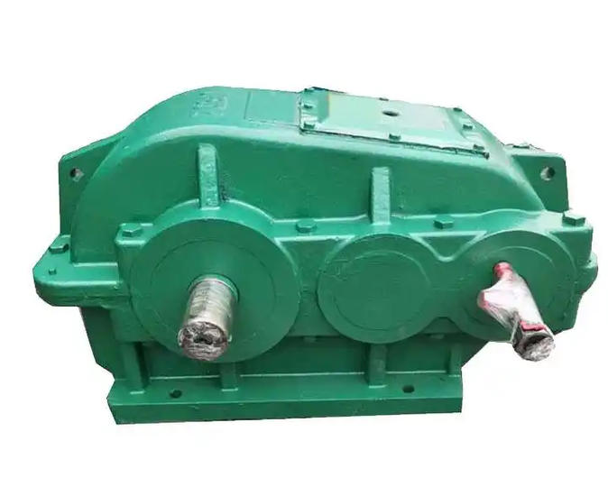
How to avoid overloading of ZQ series cylindrical gear reducers
I. Source Control: Precise Model Selection and Calculation
- Reserve Safety Margin: During the model‑selection phase, precise calculations must be performed based on the equipment’s actual load, operating speed and shock conditions. It is recommended to reserve a 15%‑20% safety load margin on top of the rated load to prevent overloaded operation where undersized equipment handles excessive workloads.
- Address Shock‑prone Operating Conditions: For equipment subject to frequent start‑stop cycles or shock loads, select components according to the maximum instantaneous load rather than merely the rated load, and reserve a torque redundancy of 1.5‑2 times. Priority shall be given to components with high impact toughness (e.g., carburized and quenched gears).
II. Standardized Operation: Optimized Procedures and Practices
- Smooth Load Application: Formulate sound operating procedures. Prohibit abrupt load‑rising behaviours such as instant full material feeding or aggressive workpiece cutting. Operators shall increase load and material feeding volume in gradual stages.
- Prevent Improper Operations: Standardize equipment operation management. Avoid frequent load adjustments or rapid start‑stop cycles. Do not arbitrarily raise operating load to meet production demands, so that the reducer always maintains a safe operating margin.
III. Protective Retrofit: Dual Mechanical and Electrical Protection
- Mechanical Protection Devices
- Torque Limiter (Safety Clutch): When the load torque exceeds the set value (normally 1.2‑1.5 times the rated value), power transmission is automatically interrupted via friction slippage or ball disengagement to avert damage caused by overload.
- Elastic Coupling: Fit an elastic coupling or hydraulic buffer at the output end. Instant shock energy is absorbed through elastic deformation to cushion torque fluctuations and mitigate rigid shocks to the reducer.
- Electrical Protection Devices
- Overload Protection Settings: Ensure over‑current and over‑torque protection is configured in controllers (e.g., frequency converters, drives) or circuits. When sudden load growth pushes current or torque above thresholds (e.g., 1.2‑1.5 times rated values), the system shall automatically limit current or cut off output.
- Real‑time Monitoring and Early Warning: Install load‑monitoring units or torque sensors to track operating load in real time. Trigger immediate warnings and automatic shutdown upon overload to prevent component damage from sustained overloading.
IV. Emergency Response: Correct Actions for Sudden Load Surge
- Emergency Stop or Gradual Load Reduction: In the event of abrupt load increase, press the emergency‑stop button to cut power for non‑critical working conditions. For critical equipment that cannot stop abruptly, reduce load step‑by‑step via the control system (e.g., cut down feed rate) to bring down torque demand rapidly.
- Speed Reduction for Buffering: Lower the motor operating frequency via the frequency converter. Reduced rotational speed decreases shock acceleration, thereby lowering instantaneous impact force on gear meshing.
- Manual Stuck‑fault Clearance: If load rises sharply due to foreign‑object jamming, clear the obstruction manually only after power is cut off. Forced running under jamming conditions is strictly forbidden.
V. Routine Maintenance: Periodic Inspection and Servicing
- Lubrication System Assurance: Inspect and replenish high‑grade lubricating oil at regular intervals and maintain proper oil level. Insufficient lubrication raises frictional resistance, which gives rise to hidden overload and component burnout.
- Periodic Inspection and Replacement: Establish a regular inspection regime, focusing on wear of gears and bearings. Immediate replacement is required when gear wear reaches 10% of tooth thickness, or when bearings show pitting corrosion or deformed cages. This prevents overload‑induced failure stemming from degraded load‑bearing capacity of aged parts.
- Installation‑condition Check: Periodically inspect reducer anchor bolts and coupling alignment. Looseness or misalignment would introduce extra resistance and amplify vibration, which must be avoided.