

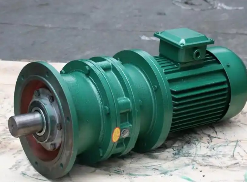
Specific repair steps for XLD5-9-Y11-ZP cycloidal pinwheel reducer slipping
Regarding the issue of "slip" in the XLD5-9-Y11-ZP cycloidal pinwheel reducer mentioned, this usually refers to the phenomenon of unstable output shaft speed, fluctuating speed, or a significant decrease in speed under load. This is not a true 'slip', but a transmission failure caused by internal wear, loose connections, or poor lubrication.Please follow the following systematic steps for troubleshooting and repair.
Safety warning: Before performing any maintenance operation, it is necessary to cut off the power supply of the equipment and hang a warning sign to ensure that the equipment is completely stopped and cooled to room temperature.
Phase 1: External Investigation
Before disassembling the gearbox, first check the external connection parts, which are often the root cause of the problem.
1. Check the coupling and key connection
Phenomenon: Loose coupling between the motor and reducer, or worn or loose keys and splines connecting the output shaft to the load, can lead to insufficient torque transmission and result in "slipping" phenomenon.
Operation: Check if all connecting bolts are tightened. Check whether the flat keys or splines are worn, deformed, or loose.
Repair: Tighten loose bolts. If the key or keyway is worn, it is necessary to replace the key with a new one or repair the keyway.
2. Check the lubricating oil
Phenomenon: Lack of oil or incorrect lubricant grade can lead to poor lubrication of internal parts, increased friction, and decreased efficiency.
Operation: Check if the oil level is within the normal range and confirm if the viscosity grade of the lubricating oil meets the equipment requirements.
Repair: Supplement or replace with the correct lubricating oil.
Phase 2: Disassembly and Internal Maintenance
If the external investigation does not solve the problem, the gearbox needs to be disassembled and repaired.
1. Disassembly steps
(1) Oil draining and cleaning: Drain the old oil from the gearbox and clean the casing.
(2) Separate motor: Remove the bolts connecting the motor and gearbox, and separate them.
(3) Dismantling end cover: Loosen and remove the bolts of the bearing end cover diagonally and evenly, and remove the end cover.
(4) Remove the output shaft: Remove the retaining ring from the bearing and then withdraw the output shaft from the machine base.
(5) Disassemble the deceleration core components:
Remove the retaining ring above the bearing.
Use a specialized tool (such as a puller) to remove the bearing. Attention: It is strictly prohibited to directly strike with a hammer to avoid damaging the parts.
Remove the inner roller (rotating arm bearing).
Key step: Before removing the cycloidal gear above, be sure to wipe the surface clean and remember the position of its numerical mark. Then find the mark on the cycloid wheel below and remember its position as well. The markings on the two cycloidal gears are usually installed symmetrically at 180 ° to each other, which is the key to ensuring correct meshing.
Take out the spacer ring, eccentric sleeve, and the cycloid wheel below in sequence.
Finally, remove the needle tooth shell and take out the needle tooth pin and needle tooth sleeve.
Related News


