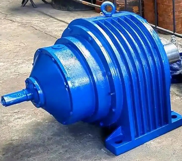


What Is the Assembly Tolerance for Full Overlap of BWD12 23 1.5KW Cycloidal Gear Reducer
There is no separate dedicated standard governing assembly tolerances for the BWD12-23-1.5KW cycloidal reducer with fully overlapping cycloidal gears. Its assembly complies with general tolerance specifications for cycloidal gear reducers, detailed below:
Phase Tolerance: Precise phase difference must be maintained when installing the double cycloid gears. Normally, the second set of cycloidal gears shall be rotated 180° relative to the first set. A phase detector is commonly used for verification, and the angular error of the eccentric sleeve shall be ≤ 0.01°.
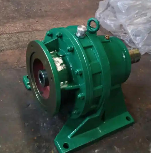
Mesh Clearance Tolerance: After assembly, inspect the meshing clearance between cycloidal gears and needle teeth using a feeler gauge. The specified range is 0.05–0.08 mm.
Geometric Tolerance: Roundness and cylindricity of bearing mating holes shall meet IT7 grade or higher. The radial runout of the pin-hole center circle relative to the bearing axis shall be IT7 grade or higher. The perpendicularity of gear working tooth surfaces against the reference end face shall be IT6 grade or higher. The perpendicularity of pin-hole axes to the reference end face shall be IT6 grade or higher, and the parallelism between the two end faces shall also meet IT6 grade or higher.