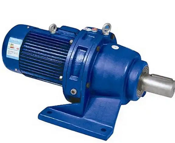
What details should be paid attention to when adjusting the radial clearance of the cycloidal gear of BWD16-23-18.5KW reducer
Adjusting the radial clearance of the cycloidal gear of BWD16-23-18.5KW reducer requires focusing on the four details of "precise measurement, standardized operation, synchronous calibration, and safety protection" to avoid abnormal meshing or component damage caused by improper operation.1、 Key details of the measurement process
Before measurement, it is necessary to thoroughly clean the cycloid wheel, needle ring gear, and needle surface, remove oil stains, iron filings, and other impurities to avoid affecting the accuracy of the clearance value.
Select a range adapted feeler gauge (recommended 0.02-1mm), evenly select 4-6 measuring points in the circumferential direction, take the average as the actual gap, and do not miss any local deviations.

When measuring, the insertion force of the feeler gauge should be moderate to avoid deformation of the tooth surface caused by a hard plug, while ensuring that the feeler gauge is perpendicular to the meshing surface to reduce measurement errors.
Record the initial gap value, compare it with the standard range in the instruction manual (usually 0.1-0.3mm), clarify the thickness of the gasket that needs to be adjusted, and do not blindly increase or decrease it.
2、 Operation details of assembly adjustment
The gasket should be made of the same material and thickness of flat parts. It is forbidden to use damaged, deformed, or multi-layer thin gaskets as substitutes to avoid uneven gaps.
When adding or removing shims, they should be evenly distributed around the circumference of the end cap or machine base to ensure that the force is balanced after the end cap is tightened, and not cause axial displacement of the cycloid wheel.
When tightening the end cap bolts, use a diagonal uniform tightening method, gradually apply force in 2-3 times, and the torque should meet the requirements of the instruction manual (usually 25-40N · m) to avoid excessive force on one side.
After adjustment, manually rotate the input shaft and feel whether the resistance is uniform throughout the entire process, without any jamming or local tightness. At the same time, observe whether the meshing contact marks between the cycloid wheel and the needle teeth are uniform.
3、 Synchronization calibration details of associated components
When adjusting the radial clearance, synchronously check the axial displacement to ensure it is within the range of 0.05-0.15mm, to avoid radial adjustment affecting axial stability.
Verify the coincidence status of the cycloidal gears, ensuring that the two cycloidal gear tooth profiles and pin holes are completely aligned without phase misalignment. Otherwise, the clearance needs to be adjusted after repositioning.
Check the wear of the eccentric sleeve and eccentric bearing. If the bearing clearance exceeds the standard (more than 0.05mm), replace the bearing first and adjust the radial clearance to avoid linkage effects.
Confirm that the needle ring is securely installed without looseness or deviation, and that the needle teeth are not deformed or detached. Otherwise, it may cause abnormal meshing even after adjusting the clearance.


