

List the main parameters of NMRV130-80-3KW aluminum alloy worm gear reducer
The main parameters of NMRV130-80-3KW aluminum alloy worm gear reducer are as follows:1、 Basic model and core specifications
Model: NMRV130-80-3KW (NMRV is the series code, 130 is the base number, 80 is the nominal reduction ratio, 3KW is the adapted motor power)
Suitable motor power: 3KW (mainly three-phase asynchronous motor, can be adapted to servo motor, speed regulating motor, etc.) [4]
Nominal reduction ratio: 80 (one of the NMRV130 series standard reduction ratios, with a range of 5-1000, and commonly used standard ratios including 80) [3] [4]
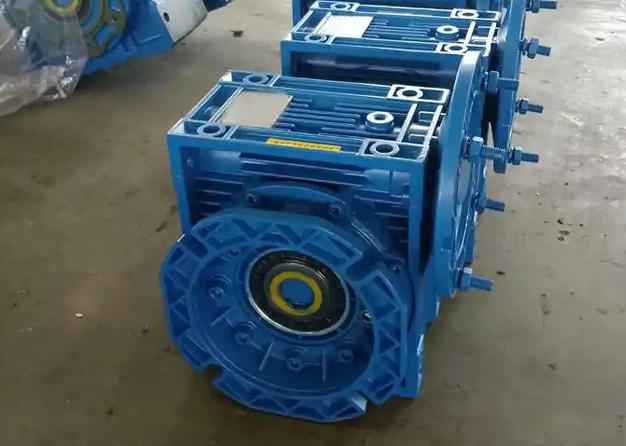
Structure type: single-stage worm gear transmission, 90 ° right angle output, compact structure
2、 Material parameters
Shell material: Made of high-strength aluminum alloy die-casting, light weight, strong corrosion resistance, high heat dissipation efficiency, beautiful and durable (NMRV130 machine base parts are made of cast iron, aluminum alloy material is customized, suitable for lightweight needs)
Worm material: 20Cr, treated with carburizing and quenching, with a tooth surface hardness of 56-62HRC, and a carburizing layer thickness of 0.3-0.5mm after precision grinding. It has high transmission accuracy and strong wear resistance
Worm gear material: wear-resistant tin bronze (some manufacturers use nickel bronze alloy), suitable for worm gear transmission, reduces wear, and extends service life
3、 Transmission and torque parameters
Output torque: Combined with a 3KW motor and an 80 reduction ratio, the rated output torque is approximately 220-300N · m (the specific value may vary slightly due to the manufacturer's process, and the maximum allowable torque can reach 1550N · m, with short-term impact torque not exceeding 1.5 times the allowable torque)
Transmission efficiency: After the break in period, the dynamic efficiency is ≥ 0.4 (meeting the dynamic self-locking condition, and the output shaft stops synchronously when the input shaft stops), and the static efficiency is ≥ 0.5 (meeting the static unlocking condition)
Input speed: Suitable for motor standard input speed (usually 1450r/min, adjustable according to motor specifications)
Output speed: approximately 18.1r/min (calculated based on an input speed of 1450r/min and a reduction ratio of 80, 1450 ÷ 80 ≈ 18.1r/min)
4、 Installation and output parameters
Installation method: Supports flange installation and base installation, can be installed in all directions, suitable for different equipment installation needs
Output mode: Solid shaft, hollow shaft, dual output shaft, flange output (default solid shaft, can be customized according to needs)
Input parameters: The standard input shaft diameter is commonly 35mm/40mm (slightly different from different manufacturers), suitable for 3KW motor flange size, and can be connected through a coupling transition
Maximum radial load: approximately 16500N (subject to actual measurement data from the manufacturer)
Related News


