
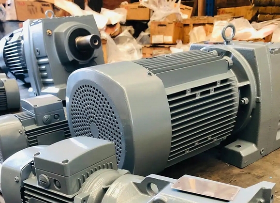
Methods to determine stable operation status for K107 YVP18.5 42.33 M1 B 270 gear reducer
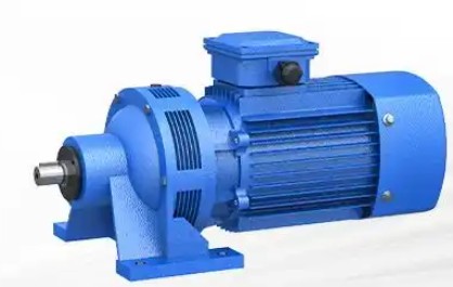
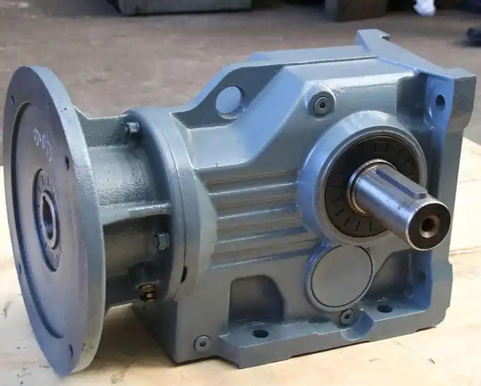
This K-series helical-bevel gear reducer is matched with an 18.5 kW variable frequency motor. It features a reduction ratio of 42.33, horizontal mounting configuration and an output shaft orientation of 270°. To assess the stability of its operating conditions, evaluations can be carried out from three aspects: operational status observation, parameter data acquisition and fault feature identification. The detailed procedures are listed below.
1. Operational Status Inspection via Sensory Observation
Noise inspection: In stable normal operation, the reducer produces even, low-volume gear meshing sound with no prominent abnormal noise. Periodic clicking impact noise, sharp whistling or random irregular sounds point to improper gear meshing, bearing failure or coaxiality offset, meaning unstable operating conditions.
Vibration inspection: Manually touch the reducer housing. Stable operation brings minor vibration with no noticeable shaking. Severe housing vibration, obvious hand numbness during contact or visible radial runout at the output shaft end may stem from loose base fastening, uneven gear abrasion or rotor imbalance, which are signs of abnormal operation.
Temperature rise inspection: After continuous operation for 1 to 2 hours, measure the housing temperature with a thermometer. Normal temperature rise should not exceed 40 ℃ relative to ambient temperature, and readings should stay steady without continuous growth. Local overheating above 80 ℃ or a rapid temperature rise rate suggests insufficient lubrication, overload operation or impaired heat dissipation, indicating unstable working conditions.
2. Acquisition of Core Parameter Data
Speed stability: Read the output speed from the variable frequency motor controller. Under stable operating conditions, the actual speed shall match the set value with fluctuation limited within ±2%. Frequent high-low speed swings, especially speed drift under low-frequency operation, are caused by excessive load variation or mismatching between the motor and reducer.
Current monitoring: Fit an ammeter on the motor input side. During stable operation, the running current should remain steadily between 70% and 90% of the rated current without large fluctuations. Frequent overload current peaks exceeding 1.5 times the rated current or current variation over ±15% means the reducer bears overload or shock load, leading to unstable working conditions.
Lubricant condition monitoring: Take lubricating oil samples periodically. Under stable operation, the oil remains transparent, free from metallic particles, emulsification and degradation. Cloudy and blackened oil mixed with iron or copper powder, or oil with emulsification and stratification, indicates heavy wear on gears and bearings, representing abnormal operating conditions.
3. Fault Feature Identification and Working Condition Correlation
Heavy vibration occurring at startup that eases slightly after running usually results from excessive starting shock load or coupling coaxiality misalignment. This is classified as short-term instability, requiring adjustment of the load startup mode.
If vibration and noise grow gradually after a period of operation together with rising temperature, the root cause is mostly lubricant degradation or enlarged gear meshing clearance. The working state shifts progressively from stable to unstable, and immediate shutdown maintenance is required.
Resonance noise emerging during variable frequency speed regulation generally happens when the operating speed approaches the reducer’s natural frequency. This counts as instability under variable-speed operation, and the resonant speed range must be avoided.