

How to use a frame level to check the levelness of the motor and ZDY355-3.55-II reducer
The use of a frame level for testing requires following the process of "selecting accuracy+cleaning positioning+multi-faceted detection+reading calibration" to ensure accurate longitudinal and transverse horizontal data, while also linking coaxiality assistance for judgment.1、 Preparation before testing
Choose a frame level that is suitable for accuracy, with priority given to the 0.02mm/m specification, to meet the detection accuracy requirements of the ZDY355-3.55-II reducer and motor.
Shutdown and power off, wait for the equipment to cool down, avoid high temperatures affecting detection accuracy, and ensure that the equipment is completely stationary.
Clean the testing surface and use a cloth to wipe away oil, dust, and iron filings from the motor base, reducer base, and two equipment shaft end faces, ensuring that the level gauge is tightly adhered to the testing surface without any gaps.
Check the status of the level, ensure that the bubble tube is not damaged and the bubbles are clear, and calibrate the zero point of the level in advance on the standard plane (with the bubble centered as the reference).
2、 Specific testing steps
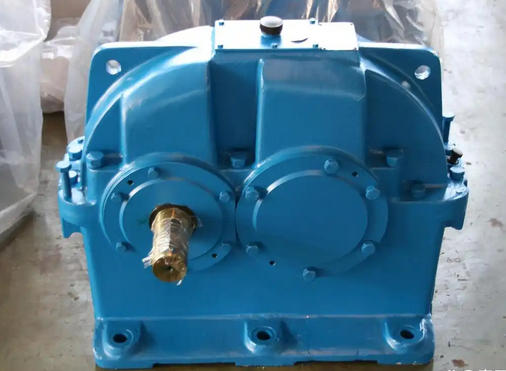
Check the levelness of the gearbox
Horizontal inspection: Place the level on the horizontal plane of the reducer base (perpendicular to the axis direction), gently press the level to ensure proper fit, observe the direction and number of bubbles offset, and record the reading (1 grid corresponds to a deviation of 0.02mm/m).
Longitudinal inspection: Rotate the level by 90 ° and place it on the longitudinal plane of the reducer base (parallel to the axis direction). Repeat the above operation and record the longitudinal deviation data.
Shaft end verification: Place the level gently on the input shaft end face of the reducer (ensuring that the shaft end is flat), check the levelness of the axis, and verify it with the base detection data.
Check the levelness of the motor
Using the reducer as a reference, measure the horizontal and vertical levelness of the motor base using the same method and record the corresponding readings.
Similarly, place a level on the end face of the motor output shaft to check the levelness of the motor axis and ensure that it is consistent with the horizontal trend of the reducer axis.
Data calibration and review
Repeat the measurement 2-3 times for each detection surface, take the average to reduce errors. If the reading deviation is large, the detection surface needs to be cleaned again before measurement.
Comparing the levelness data of the motor and reducer, the longitudinal and transverse deviations should be ≤ 0.05mm/m (i.e. the bubble offset should not exceed 2.5 grids), and the levelness deviation of the shaft end should be consistent with the base deviation.
3、 Key operational points
When placing the level, handle it gently to avoid colliding with the detection surface or the level itself, and to prevent affecting the accuracy.
When reading, keep your line of sight perpendicular to the bubble tube to avoid reading errors caused by viewing angle deviation.
If there is slight unevenness on the detection surface, a layer of thin paper (thickness ≤ 0.01mm) can be placed to ensure adhesion, but multiple layers or thick pads should not be placed to avoid interfering with the data.
After the inspection is completed, clean the level in a timely manner and store it in a dry environment to avoid moisture or collision that may affect the accuracy.
