

ZZSH Three Ring Reducer Installation and Debugging Guide, Standardized Operation, Extended Equipment Life
The standardization of installation and commissioning of ZZSH three ring reducer, as the core transmission component of pile drivers, directly affects the stability and service life of equipment operation. The working conditions of pile foundation engineering are complex and the load impact is large. If installed and debugged improperly, it is easy to encounter faults such as oil leakage, abnormal noise, and insufficient torque, which seriously affect the construction progress. This article provides a detailed explanation of the standardized operation process of ZZSH three ring reducer from three aspects: pre installation preparation, installation steps, and debugging points.1、 Preparation before installation: control details and avoid hidden dangers
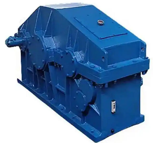
1. Equipment inspection: Check whether the reducer model (such as ZZSH400, ZZSH450) and parameters match the requirements of the pile driver; Check if there are any bumps or cracks on the box and shaft ends, if the seals are intact, and if the fasteners are loose;
2. Environmental cleaning: The installation area should be kept dry and clean, free of dust and debris, to prevent impurities from entering the reducer and causing wear and tear;
3. Preparation of tools and accessories: Prepare wrenches, torque wrenches, level gauges, non rigid couplings, N110-N200 medium extreme pressure gear oil to ensure that the tools are in good condition and the accessories are compliant;
The installation base of the pile driver should be flat and sturdy, with a flatness error of ≤ 0.1mm, to avoid uneven stress and deformation of the reducer after installation.
2、 Installation steps: step-by-step operation, precise and accurate
1. Positioning installation: Place the reducer steadily on the base of the pile driver, adjust the position so that the output shaft is parallel to the axis of the drill rod, and the input shaft is strictly aligned with the axis of the motor, with a coaxiality deviation of ≤ 0.1mm;
2. Fixed fastening: Use high-strength bolts to fix the reducer base, and tighten the bolts evenly in stages to avoid deformation of the box due to local stress;
3. Coupling installation: Non rigid couplings are selected to connect the input shaft of the reducer to the motor shaft, and the output shaft to the drill rod. The gap between the couplings is controlled at 2-3mm, and the bolts are symmetrically tightened to prevent eccentric vibration during operation;
4. Lubricating oil filling: Open the oil level plug and add N110-N200 medium extreme pressure gear oil to the middle of the oil level line. It is strictly prohibited to have the oil level too high or too low. After filling, tighten the oil level plug and vent plug.
3、 Debugging points: No load+load, gradually verify
1. No load debugging: After installation, manually rotate the high-speed shaft to ensure that the low-speed shaft rotates flexibly in both directions without any jamming; Start the motor and run it without load for 2 hours. Check for any abnormal noise, oil leakage, or vibration. The oil temperature should be ≤ 60 ℃ and the temperature rise should be ≤ 40 ℃;
2. Load debugging (step-by-step loading): After the no-load is normal, load gradually at 25% → 50% → 75% → 100% of the rated load, run each level for 30 minutes, and observe:
Operating status: stable without impact or abnormal noise;
Oil temperature: maximum ≤ 80 ℃, temperature rise ≤ 60 ℃;
Sealing: No oil leakage phenomenon;
Related News


