

Overview
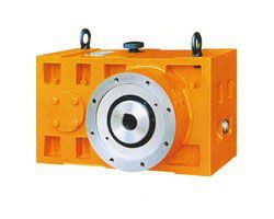
ZLYJ series reducer is a high-precision hard-toothed belt thrust seat transmission component designed for plastic screw extruder. The product design adopts the technical specifications specified in JB/T8853-2001. It features high-strength alloy steel for gear and shaft parts. The gear is processed by carburizing, quenching and grinding. Gear accuracy is GB10095-88.6. Tooth surface hardness HRC54-62. An over-sized thrust bearing is arranged at the front end of the hollow output shaft to withstand the working axial force of the screw. The main standard parts such as bearings and oil seals are made of domestic high-quality products, and can also be equipped with imported products according to user needs. The whole machine has the characteristics of small volume, high carrying capacity, stable transmission, low noise and high efficiency. The product performance has reached the international advanced level and can replace the same type of imported products.
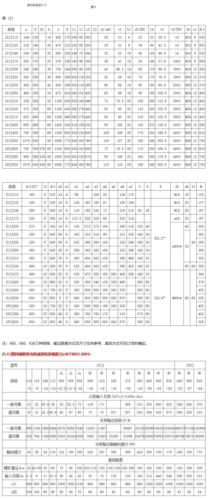
The specifications and gear ratios in this series are common data for existing users. When the user selects, the actual transmission torque of the screw and the allowable output torque listed in Table (2) can be selected. If it is necessary to match the rubber extruder, the impact of the rubber extruder is stronger than that of the plastic. Please ask the user for specific technical parameters.
ZLYJ塑料橡胶挤出机减速机适用条件及减速机代号和标志(JB/T8853-2001)

适用条件
1、减速机高速轴转速不大于1500r/min
2、工作环境温度为0~35℃。当温度超出本规定时,可按用户要求,另行配置润滑加热或冷却装置。
减速机代号和标志
在减速机代号中,包括型号、输出级中心距、公称传动比、装配型式。
标主示例
ZLYJ塑料橡胶挤出机减速机外形尺寸及装配型式(JB/T8853-2001)


Note: 1, △ - with cooling, * - with cooling and forced oil circulation. 112, 133, 146, 173 do not need to be cooled when pre-selected according to high reliability.
2. The input power and output torque of the table have been considered for the working condition coefficient and can be directly selected.
3, the table output torque is the main selection basis. The gear ratio can be adjusted according to user needs. The i of ZLYJ is 6.3-20.
4. When the bearing load factor fd=1.5 is taken, the axial thrust and the output shaft given rotational speed are calculated according to the table. The theoretical calculation life of the thrust bearing is about 12,000 hours except for 133 and 146. Both are around 25,000 hours.
5. Check the cooling design parameters of the reducer in the following cases:
5.1 is selected according to high reliability data, but the output speed exceeds the table (2)n (ie, the input power is increased).
5.2 According to the general reliable selection, when the input power is increased.
5.3 When the cooling area of the internal cooling method is insufficient, an external oil cooler with an oil pump is used. The use of a cooler is additionally stated at the time of ordering.
ZLYJ plastic rubber extruder reducer lubrication, cooling and heating (JB/T8853-2001)
Gears and bearings are lubricated with oil pools and splashes. In addition to splash lubrication, bearings of ZLYJ280 and above have increased the forced circulation lubrication of the oil pump lubrication system. , ,
The lubricating oil grade is medium-grade pressure gear oil N220 or other high-quality lubricating oil with similar viscosity.
When the ambient temperature is lower than 0 °C, an electric heating pipe is added to the oil pool to preheat the lubricating oil.
When the ambient temperature is above 35 °C, the manufacturer shall perform a heat balance calculation based on the temperature value provided by the user to determine whether to increase the cooling device.
Installation and maintenance of ZLYJ plastic rubber extruder reducer (JB/T8853-2001)
1. The reducer should be installed on a flat basis. When the anchor bolts are evenly tightened, the screw inserted into the output shaft should be able to rotate evenly without any jam, so as to avoid adding additional stress to the output shaft bearing and affecting the bearing. life. Do not use strong fastening screws.
The power input of the gearbox of 420 or higher (including 420) is only allowed to input power with the coupling. When installing, ensure that the coupling error of the coupling does not exceed the allowable range with the anchor bolts tightened. It is not allowed to center the coupling and tighten the anchor bolts when unbalanced foot support, so as not to cause excessive additional torque to the input shaft. If the user really needs to use the V-belt input power, please make this request clearly when ordering!
The 375 or less (including 375) specification allows the use of a V-belt to input power. Please try to use high-strength narrow V-belt! And the V-belt should be fully turned and balanced. The high-strength narrow V-belt is used to reduce the tension and bring the center of the force closer to the inside of the input shaft. It is advantageous to reduce the additional bending moment acting on the outer surface of the front bearing fulcrum. Under the initial installation of the V-belt, the midpoint of the tight side of the V-belt is pressed under 2-3 kg of external force, and 8-10 mm deformation can occur.
Due to the small center distance of the hardened gear reducer, large bearings cannot be configured and the journal is also thin. Whether the alignment of the coupling and the tension of the V-belt meet the above requirements will directly affect the input shaft and bearing, and even the life of the whole machine!
2. After the gear unit is installed, the oil is injected to the oil level on the oil mark. The oil level should be determined after the lubricating oil is evenly distributed in the tank. The oil level should be inspected frequently. Under any circumstances, the oil level should not be lower than the lower oil mark position. After using for 300 to 600 hours for the first time, the oil should be changed once. Change oil every 3,000 hours later. The replacement should be stopped at the gear unit and discharged when the oil has not cooled. The cabinet is rinsed with the same quality oil. If it is not suitable for washing due to high viscosity, it can be heated first.
In an oil circuit with forced lubrication. It is equipped with a TF-type self-sealing suction filter with extremely advanced functions. The filter has the following functions: (1) Opening the front cover, when the filter element is removed, the built-in self-sealing valve will close itself, cut off the oil circuit, and prevent oil from flowing out of the oil tank. (2) The transmitter with green, yellow and red ribbons can display the filter plugging status at any time (green-clear, yellow-partial blockage, red-severe blockage). When there is a serious blockage, the transmitter will send a signal (please connect the two output terminals of the transmitter to the alarm line) to remind the user to stop cleaning or replace the filter. (3) After the message is sent, the user still does not clean. When the filter element is further blocked, the bypass in the filter is opened by itself, and the lubricating oil will not circulate through the filter core.
The electric contact pressure gauge configured according to the user's special requirements can monitor the working state of the oil pump. When the oil pump is damaged, the oil circuit stops supplying oil, and when the electric contact pressure gauge loses pressure, the pressure gauge will have an electric signal output. At this point, the control circuit will automatically alarm, cut off the power supply, stop the maintenance, so as to avoid the upper bearing lack of oil and burn.
In order to avoid the motor at the moment of starting, the oil pressure gauge is turned off due to the instantaneous oil flow and the power supply is reversed. It is recommended to set the time delay breaker in the motor control loop to ensure the normal start of the motor.
The electric contact pressure gauge has been adjusted to 0.3~0.4Mpa before the factory leaving the factory. (The upper pressure pointer does not need to be adjusted.) After running for a period of time, the viscosity will drop due to oil heat, and the oil pressure may drop. normal work. At this time, loosen the lock nut on the side of the table and adjust the pressure adjustment screw (screw in) with a screw to raise the oil pressure. After adjusting the pressure, please lock the nut. The alarm control circuit described above needs to be configured by the user. This device only provides the relevant components that can output the electric number.
3. The speed reducer equipped with forced lubrication of the oil pump may cause excessive oil shortage due to excessive oil viscosity and high oil absorption resistance of the oil pump in the initial stage of driving, and excessive noise is emitted. This phenomenon generally disappears after the temperature of the lubricating oil rises.
In normal operation, if there is an increase in the noise of the oil pump, the general situation may be that the oil path resistance is too large. In this case, clean the filter and other related components.
No matter which type of reducer is used, it should be operated for a period of time when it is not used for a long time or when the temperature is too low. It can be loaded after the bearings are fully lubricated.