
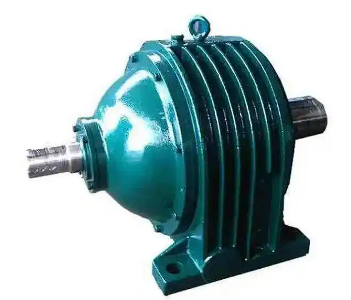
How to Adjust the Coaxiality of NGW72-90-11kw Planetary Gearbox Exceeding Tolerance
The following are the specific adjustment steps and technical requirements:1、 Preparation and accuracy standards before adjustment
1. Stable foundation: Stop the machine and turn off the power, check if the installation base of the reducer and motor is firm, and ensure that the overall base is not loose or suspended. The flatness of the base should be ≤ 0.1mm/m2.
2. Cleaning the shaft end: Clean the anti rust oil, dust, and burrs on the mating surfaces of the motor shaft, reducer input shaft, and coupling to avoid impurities affecting measurement and fitting accuracy.
3. Accuracy standard:
Normal operating conditions: The coaxiality deviation should be controlled within ≤ 0.2mm.
Precision transmission scenario: Radial deviation should be strictly controlled within ≤ 0.03mm, and angular deviation should be ≤ 0.03mm/100mm (some high-precision requirements require ≤ 0.02mm).
2、 Measurement and data recording
1. Set up a dial gauge: fix the magnetic dial gauge holder on the reference shaft (or motor shaft) of the gearbox, and install two dial gauges:
Radial table: The header is vertically placed on the outer circular surface of the coupling, with a downward pressure of about 2mm.
End face table: The header is vertically pressed against the end face of the coupling, with a downward pressure of about 2mm.
2. Turning reading: Slowly rotate the shaft body once, record the radial and end face dial gauge readings at four positions: 0 °, 90 °, 180 °, and 270 °, and determine the magnitude and direction of the misalignment.
3、 Core adjustment steps
When adjusting, the gearbox is usually used as a reference, and the motor base is adjusted to calibrate:
1. Radial deviation adjustment (height and left-right misalignment):
High and low deviation: Adjust the thickness of the gasket at the motor foot screw based on the difference between the readings on the dial gauge. For example, if the motor is low, calculate the difference and raise it accordingly; In experience, an additional shim of 0.10~0.15mm can be added to compensate for the sinking during fastening.
Left and right deviation: Slowly move the motor horizontally for fine adjustment, and it is strictly prohibited to forcefully pry the transmission shaft to avoid bending and deformation of the shaft body.
2. End face deviation adjustment (angle tilt):
If the end face runout exceeds the standard, it indicates that the two axes are not parallel. It is necessary to calculate the increase or decrease of the front and rear foot pads based on the principle of similar triangles, and correct the tilt angle of the shaft by adjusting the thickness difference between the front and rear pads of the motor.
Repeated review: After adjusting the gasket or moving the position each time, it is necessary to re turn and mark the gauge until the radial and end face runout meet the standards.
4、 Tightening and trial operation verification
1. Diagonal segmented locking: After alignment, it is strictly prohibited to tighten a single screw at once. It is necessary to use a torque wrench to tighten the anchor bolts step by step and evenly in diagonal order to prevent the position from shifting again due to unilateral force.
2. Manual turning: After tightening, manually turn the docking shaft to confirm that the entire rotation is smooth, without any abnormal pressure or jamming sensation.
3. No load test run: Power on and conduct a low-speed test run without load to observe for any abnormal noise, vibration, or oil leakage. Monitor the temperature rise of the bearing (maximum temperature not exceeding the ambient temperature plus 40 ℃).
4. Hot retest: After the equipment reaches thermal equilibrium after running continuously for 1 hour, stop the machine and retest the coaxiality again. If the deviation rebound is caused by thermal expansion, the gasket needs to be fine tuned again based on empirical values.
Related News