
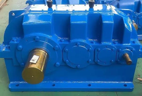
How to determine if the torque arm of CJY112 reducer is installed correctly
1、 Installation Geometry and Calibration Inspection1. Verticality/Levelness Calibration: Place a level on the reference surface of the torsion arm to ensure that the deviation in the horizontal or vertical direction is controlled within ≤ 0.1 °/m. This can effectively avoid additional bending moments caused by "inclined forces" during operation, thereby accelerating fatigue damage.
2. Installation angle confirmation: Ensure that the angle between the torque arm and the centerline of the gearbox output shaft and the anchor bolt (or support point) is approximately a right angle (with a tolerance of ± 30 °).
3. Reserved space for thermal expansion and contraction: If the operating temperature of the reducer is high or in continuous operation, it is recommended to use a "long hole" design for the connection end between the torsion arm and the support structure, and reserve a margin of 2-5mm to prevent temperature changes from causing tensile or compressive deformation of the torsion arm.
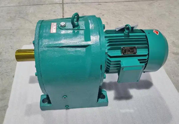
2、 Static inspection after installation
1. Appearance and connection inspection: visually inspect the torsion arm for any obvious damage, deformation, or cracks, and confirm that it is aligned with the connecting components such as the gearbox output shaft without any deviation.
2. Fastener status: Use a torque wrench to check whether all connecting bolts are tightened according to the manufacturer's recommended torque values, and confirm that anti loosening measures such as anti loosening washers or locking agents are installed in place.
3. Dimensional and clearance review: Re measure the distance (arm length) from the center of the gearbox output shaft to the torque arm support point, ensuring a deviation of ≤ 1mm from the design value; at the same time, check whether the axial and radial clearances between the torque arm, output shaft, and related components are within the allowable range.
4. Manual stability test: Shake the torsion arm by hand to confirm that there is no significant looseness or displacement.
3、 Dynamic testing during runtime
1. No load test run: Start the gearbox and run it without load for about 30 minutes, observe whether the torque arm can rotate freely, and confirm that there is no abnormal friction or noise (such as "buzzing sound" or metal friction sound). Touch the surface with your hand to confirm that there is no local overheating phenomenon (temperature should be ≤ ambient temperature+30 ℃).
2. Load test run: Gradually load at 30%, 50%, and 100% of the rated load of the equipment, and run for a period of time (such as 30 minutes to 1 hour) each time. During this period, it is necessary to focus on checking:
Bolt status: Use a torque wrench to tighten the bolt again and confirm that there is no looseness or a significant decrease in tightening torque.
Vibration and noise: Use a vibration detector to measure the vibration velocity of the support point (the standard for ordinary industrial equipment should be ≤ 4.5mm/s), and confirm that there is no abnormal vibration.
Temperature monitoring: Ensure that the surface temperature is normal after operation (usually ≤ 80 ℃), and abnormal temperature rise may indicate excessive friction or structural instability.
3. Torque transmission verification: If conditions permit, it can be confirmed through the torque sensor at the output end of the reducer that the reaction force is completely borne by the torque arm, and there is no additional torque load on the motor and coupling.
If any abnormalities are found during the above inspections or tests, the operation should be immediately stopped, the cause analyzed, and corresponding corrective measures taken to ensure the safety and reliability of the entire transmission system.
Related News