
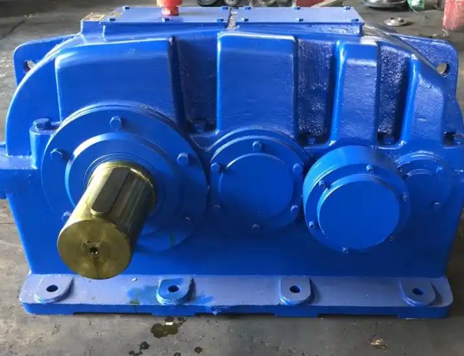
Technical Specifications & Working Principle of WPDX80-50-1.5KW Worm Gear Reducer
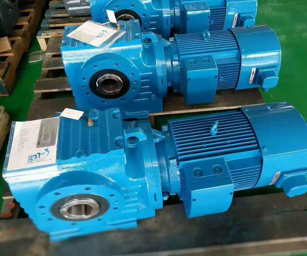
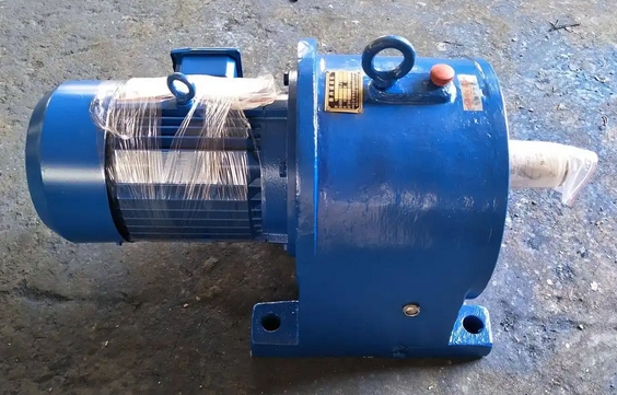
The WPDX80-50-1.5KW worm gear reducer is a widely used speed reduction unit. Its detailed description is shown below:
Technical Parameters
Input power: 1.5 kW Reduction ratio: Available standard ratios include 1:10, 1:15, 1:20, 1:25, 1:30, 1:40, 1:50, 1:60.
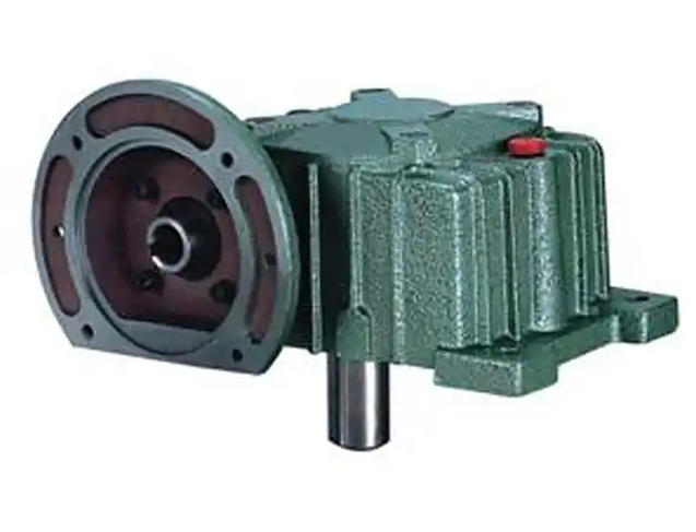
Overall dimensions: A=225 mm, AB=125 mm, BB=142 mm, BC=70 mm, CC=80 mm, M=175 mm, N=320 mm, E=140 mm, E1=130 mm, E2=150 mm, G=20 mm, Z=15 mm.
Motor flange: LA=115 mm, LB=95 mm, LC=140 mm, LE=4 mm, LZ=M8.
Output shaft: Q=31 mm, U=11 mm, T × V = 4 × 12.8 mm.
Working Principle
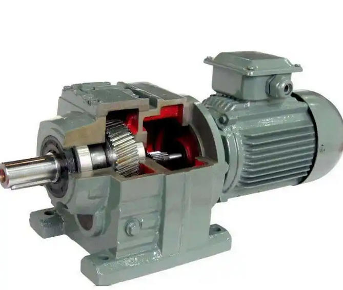
This reducer consists mainly of a worm, worm wheel, bearings and oil seals. The worm, typically manufactured from high-strength alloy steel, acts as the driving part and connects to the motor output shaft. The worm wheel, made of lower-hardness cast iron or copper alloy, serves as the driven component. As the motor spins the worm at high speed, the helical teeth of the worm engage with the worm wheel teeth. Power is transferred via meshing rotation, converting the high rotational speed of the input shaft into low-speed rotation at the output shaft to realize speed reduction and torque amplification.
Related News