

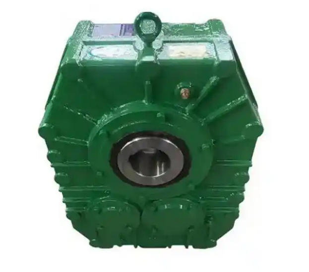
How to correct the inclination problem of the reducer shaft centerline through adjustment
To correct the inclination of the centerline of the reducer shaft, the core is achieved by adjusting the installation position of the motor/reducer through centering correction. The standard solution is to use the dial gauge calibration method, and the specific steps are as follows:1、 Preliminary preparation (laying the foundation for accuracy)
Tools and status calibration: Prepare a calibrated dial gauge (zero error ≤ 0.01mm), magnetic gauge holder, stainless steel adjustment gasket (0.1-0.5mm), torque wrench, etc; Clean the burrs and oil stains on the shaft surface, check that the coupling is not worn or deformed, ensure that the foundation bolts of the reducer have been tightened according to the rated torque, and the levelness is ≤ 0.1mm/m. Leave 1-2 turns of looseness for the motor foundation for easy adjustment.
Deviation determination: Measure the end face runout of the coupling in four directions (0 °/90 °/180 °/270 °) using a dial gauge. If the end face runout deviation is greater than 0.05mm/m, it can be determined that there is an inclination of the shaft centerline (angular deviation).
2、 Core calibration steps (angle first, radial backward, priority to eliminate tilt)
Following the general principle of "fixing the reducer and adjusting the motor position", the specific operation is as follows:
1. Determine the adjustment amount: Based on the gap difference between the end faces measured by the dial gauge, calculate the thickness of the gasket that needs to be adjusted: if the gap between the upper end faces is greater than that on the lower side, it indicates that the motor is tilted downwards in the axial direction, and the corresponding thickness gasket needs to be added to the front side of the motor (coupling side), otherwise the gasket needs to be reduced.
2. Step by step adjustment verification: After each adjustment of the gasket, re measure the end face runout until the end face runout deviation at the four positions is ≤ 0.05mm/m; After the tilt correction is completed, re measure and adjust the radial deviation to ensure that the total coaxiality deviation is ≤ 0.1mm.
3. Tightening re inspection: According to the principle of diagonal tightening, tighten the motor anchor bolts to the rated torque in 3 times. After each tightening, retest the deviation to confirm that the tilt deviation is still within the allowable range and that there is no jamming when manually rotating the shaft system.
3、 Optimization solutions for different scenarios
High precision/large equipment: It is recommended to use a laser centering instrument with an accuracy of ± 0.001mm, which can directly display tilt deviation and adjust direction. The efficiency is more than three times higher than that of a manual dial gauge.
Emergency low precision scenario: A level and tape measure can be used for simple calibration: first adjust the levelness deviation of the reducer and motor to ≤ 0.2mm/m through the level, then align the centerline with the tape measure and fine tune and fix it.
Tilting has caused component damage: If tilting causes fatigue of the pin shaft and wear of the bearing, the damaged components need to be replaced at the same time, and a spherical self-aligning roller bearing with a spherical self-aligning seat should be used to improve the compensation ability for small-scale tilting.
Related News


